Intelligent formed textile product continuous drying device and method

A textile product and drying device technology, which is applied in the field of textile production, can solve the problems of taking a long time, reducing the practicality of the device, and having too many guide rollers, so as to improve the drying effect and drying efficiency, ensure the aesthetics, The effect of improving convenience

Active Publication Date: 2021-12-10
JIANGSU DEHUA TEXTILES
3 Cites 0 Cited by

AI-Extracted Technical Summary

Problems solved by technology

[0003] Currently, when winding shaped textile products inside the drying device, it is often inconvenient for the operator to manually wind the shaped textile products inside the device due to the large number of guide rollers in the drying device, or it takes a long time for the operator to wind the shaped textile products inside the device. Shaped textile products are wound between the guide rollers in the drying device, which makes the continuous drying device for shaped textile products very inconvenient to use and reduces the practicability of the device; and...

Method used

Further, driving device 8 comprises the first servo motor, pulley and drive belt, the same end of two groups of rotating shafts 14 passes main body storehouse 9 and is equipped with pulley, and the outside of two groups of pulleys is jointly sheathed with drive belt, One end of the main body compartment 9 is equipped with a first servo motor, and the output end of the first servo motor is fixedly connected with one end of an adjacent group of rotating shafts 14, which helps to drive the two groups of rotating shafts 14 to rotate synchronously and in the same direction, so that the formed textile product can Pass through the interior of the device at a steady and uniform speed.
Further, drying assembly 6 comprises hot air blower 601, annular hollow storehouse 602, nozzle 603, installation pipe 604, drying storehouse 605, first air outlet 606, air outlet storehouse 607 and second air outlet 608, main body storehouse The bottom of 9 is equipped with a drying bin 605, and a hot air blower 601 is installed on the side away from the feed port 16 at the bottom of the drying bin 605, and an air outlet bin 607 is installed on the side far away from the feed port 16 inside a group of processing bins 17. The outside of the air outlet bin 607 is evenly provided with a first outlet hole 606, the bottom of one side of the main body bin 9 is equipped with an annular hollow bin 602, and the inner side of the annular hollow bin 602 is evenly provided with a second air outlet hole 608, and the inside of the drying bin 605 The top and inner bottom are symmetrically installed with installation pipes 604, and the outside of the installation pipe 604 is evenly equipped with nozzles 603. The output ends of the hot air blower 601 are respectively connected with the interior of the air outlet chamber 607, the annular hollow chamber 602 and the installation pipe 604. The control panel 4 passes through The wire is electrically connected to the hot air blower 601, and the first step of drying treatment is performed on the formed textile product by using the hot air ejected from the first air outlet 606, and then the second step of drying treatment is performed by the hot air ejected from the nozzle 603, and finally passed through The hot air ejected from the second air outlet 608 is used for drying in the third step, thereby greatly improving th...

Abstract

The invention discloses an intelligent formed textile product continuous drying device and method. The intelligent formed textile product continuous drying device comprises a main body bin, wherein two sets of supporting columns are symmetrically installed at the two sides of the bottom of the main body bin, processing bins are symmetrically arranged at the two sides in the main body bin, and rotating shafts are jointly arranged at the two ends in the processing bins; and connecting rods are symmetrically and evenly installed at the two ends of the outer sides of the rotating shafts, screen drums are jointly installed at the ends, away from the rotating shafts, of the connecting rods, and driving devices are jointly arranged at the two ends of the two rotating shafts. According to the intelligent formed textile product continuous drying device and method, through cooperative use of an extrusion assembly, a collection bin, a drying assembly, the connecting rods, the rotating shaft, the processing bins and the screen drums, a large amount of water in a formed textile product is extruded out through cooperation of first guide rollers and second guide rollers with the screen drums, and then the formed textile product is dried for three times through hot air sprayed out of first air exhaust holes, spray heads and second air discharging holes in sequence, so that the drying effect and drying efficiency of the whole device on the formed textile product are greatly improved.

Application Domain

Drying gas arrangementsDrying machines with progressive movements +3

Technology Topic

Structural engineeringManufacturing engineering +2

Image

  • Intelligent formed textile product continuous drying device and method
  • Intelligent formed textile product continuous drying device and method
  • Intelligent formed textile product continuous drying device and method

Examples

  • Experimental program(3)

Example Embodiment

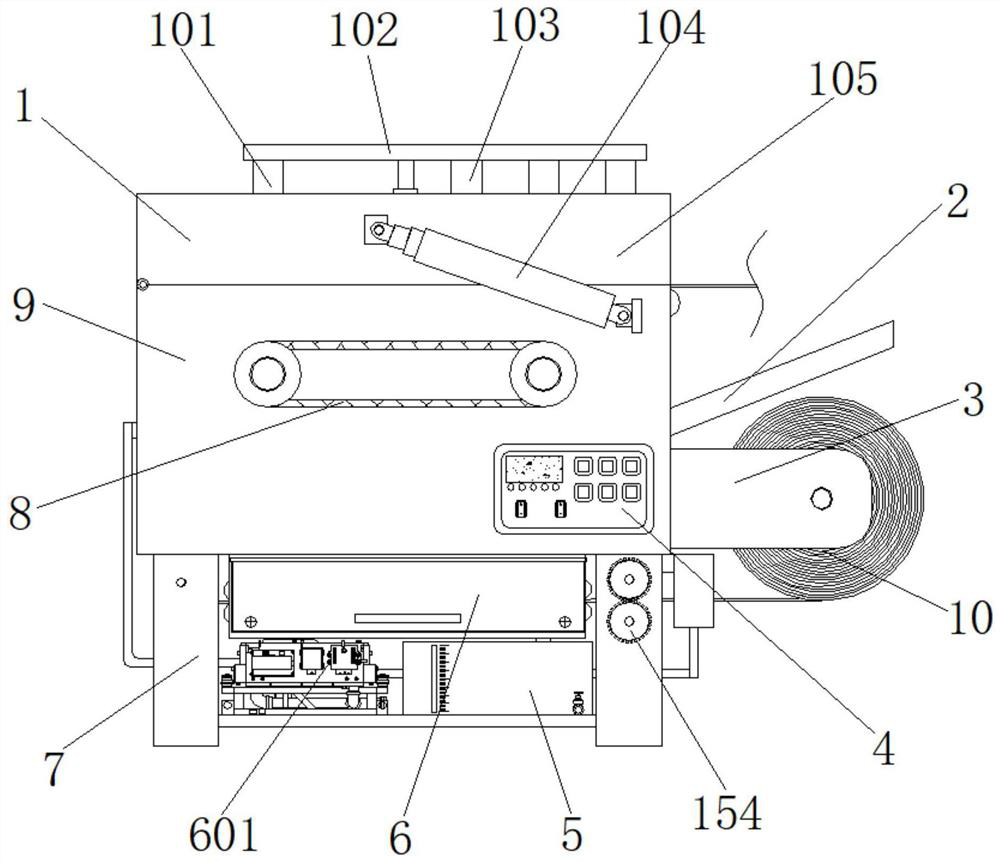
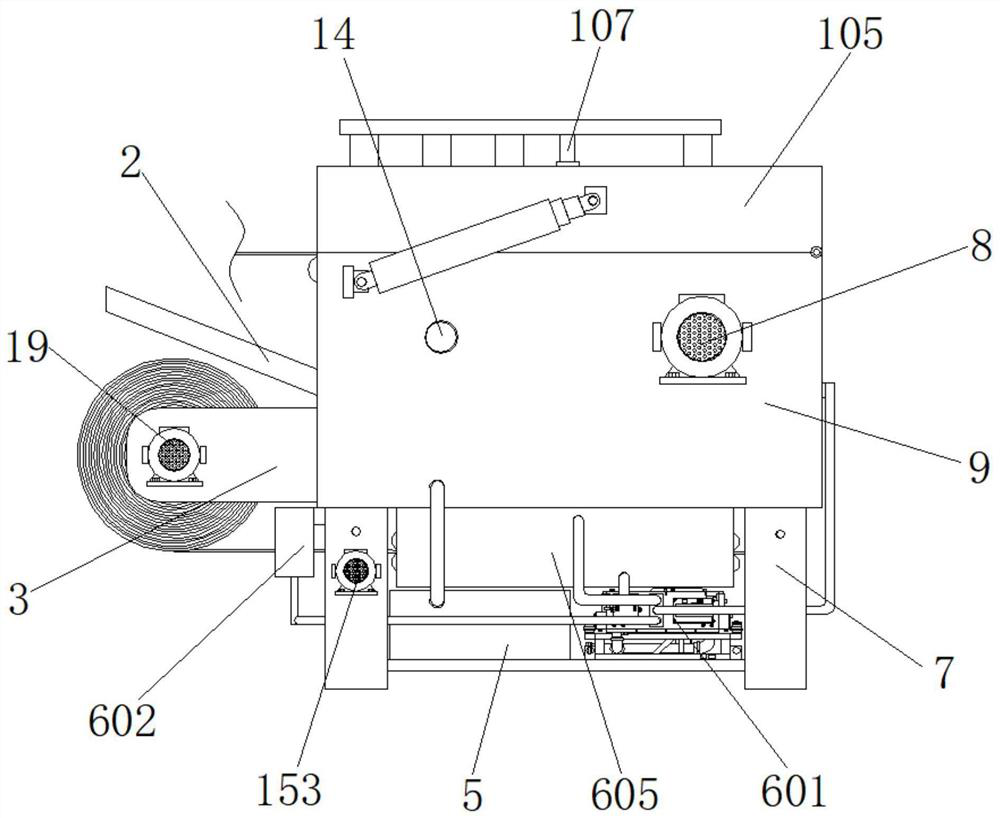
[0050] Example 1, such as Figure 1-6 As shown, when the molded textile article is needed to bypass the inner portion of the device, the electric push rod 104 is maintained by the control panel 4, so that the cover 105 is gradually opened by its hinge axis, and the molded textile product is paved in two. The top of the assembly cartridge 18 then passes through the head end of the forming textile article to the top of the drying bin 605 after the steering guide roller 12 is turned to the guide roller 12, and then the molded textile article is further passed through two sets of mounting roller 152. Between, finally, the head end of the molded textile product is fixed to the outer side of the winding roller 10 after the hollow space 602, and the control cover 105 is restored at the top of the main bin 9, and then controls the electric roses 107 to shorten, so that the first guide The roller 106 and the second guide roller 108 are close to the outer side of the two sets of sieve holes 18, and the molded textile article is clamped.

Example Embodiment

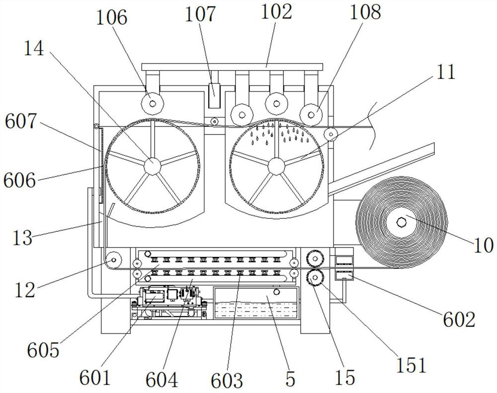
[0051] Example 2, such as Figure 1-8As shown, when the molded textile article is started, the second drive motor 19 is then controlled to start the winding roller 10 to start the winding forming textile article, and control the driving device 8 to drive the two sets of rotation 14 rotation, that is, control two groups. The screen cartridge 18 is simultaneously rotated, so that the molded textile article is uniformly passed through the inside of the apparatus, during which the first guide roller 106 and the two sets of second guide roller 108 will be formed in a forming textile article. Water extrusion, extruded water beads pass through the sieve holes on the surface of the first set of sieve holes to gradually collect the inner bottom portion of the processing bin 17, and flow into the inside of the collecting bin 5 through the pipeline, and then extruded forming textile products When the second set of screen cartridges 18 is passed, the heat fan 601 delivers hot air to the inside of the air bin 607, and the hot air inside the air bin 607 is sprayed into the outer side of the second set of frame 60 through the first air hole 606. The surface of the textile article, the first step drying treatment is carried out, and when the molded textile article enters the interior of the drying bin 605, the hot air discharged from the nozzle 603 is a second step drying process, and then the processing assembly 15 pairs The surface of the formed textile article is brushing, and then the molded textile article is formed by the second air hole 608, which is the third step drying process, and finally rotated the winding roller 10. The dry molded textile products will be harvested.

Example Embodiment

[0052] Example 3, such as figure 1 , 2 , 3, 4, 5, and 9, when it is necessary to ensure the flexibility of the surface of the formation of the textile article, control the first driving motor 153 to rotate a set of mounting rollers 152, and the two sets of mounting rollers 152 are passed through two sets of gears 154. The transmission allows the two sets of mounting rollers 152 to rotate, and the fluff processed by bristles 151 outside the mounting roller 152, and then cooperate with the second air hole 608, the hot air is blown out, greatly ensures forming textile. The softness of the surface of the article is soft, thereby ensuring the aesthetics of the forming textile products.
[0053] Working principle: Turn the device before use, when the molded textile article is needed to bypass the inside of the device, first control the electric push rod 104 by the control panel 4, so that the cover 105 is gradually opened by its hinge shaft, and then Manually put the molded textile article on the top of the two sets of sieve barrel 18, then the head end of the molded textile article is passed through the strip through hole 13 and then entering the inside of the drying bin 605 after the steering guide roller 12, and then molded textile The article is again passed between the two sets of mounting rollers 152, and finally, the molded textile product head end is fixed to the outer side of the winding roller 10 after the annular hollow 602, and the control cover 105 is restored at the top of the main bin 9, and then controls the electric lifting and land. The rod 107 is shortened, allowing the first guide roller 106 and the second guide roller 108 to close the outer side of the two sets of sieve cartridge 18, and the molded textile article is sandwiched; when the molded textile product is started, the second The drive motor 19 drives the winding roller 10 to start the winding forming textile article, and control the driving device 8 to rotate the two sets of rotation shafts 14, that is, the two sets of screen cartridge 18 are synchronized to rotate, so that the molded textile product is uniformly passed through the inside of the device, In this process, the first guide roller 106 and the two sets of second guide roller 108 are extruded out of the molded woven article, and the extruded water bead is extruded, and the extruded water bead is surfaced through the first set of screen cartridges 18. The screen is gradually collected into the inner bottom of the processing warehouse 17, and flows into the inside of the collecting bun 5 through the pipe, and then the extruded molded textile article is subjected to the heat fan 601 to control the hot air supply. Between the inside of the air storage 607, the hot air inside the air storage 607 is sprayed by the first air hole 606 in the outer surface of the forming textile article, and the first step drying process is performed, and the forming textile article is followed. When the inside of the drying bin 605 is entered, the hot air discharged from the nozzle 603 is a second step drying process, and then the processing assembly 15 bristles the surface of the passage forming textile article, and then the forming textile article is in the annular hollow. In the inside of 602, the hot air discharged by the second air hole 608 is a third step drying process, and finally the dried molded textile product is wrapped by the rotating winding roller 10; when the surface of the forming textile product is required When the softness is flexible, the first drive motor 153 controls the two sets of mounting rollers 152 to rotate, and the fluff in the surface of the molded textile article is carried out by bristles 151 outside the mounting roller 152, and the second air hole 608 is inclined to blow out heat. Air, there is greatly to ensure the softness of the surface of the forming textile article, thereby ensuring the aestheticity of the molded textile article.

PUM

no PUM

Description & Claims & Application Information

We can also present the details of the Description, Claims and Application information to help users get a comprehensive understanding of the technical details of the patent, such as background art, summary of invention, brief description of drawings, description of embodiments, and other original content. On the other hand, users can also determine the specific scope of protection of the technology through the list of claims; as well as understand the changes in the life cycle of the technology with the presentation of the patent timeline. Login to view more.

Similar technology patents

Transmission-type display

ActiveUS20160320623A1improve convenience
Owner:SEIKO EPSON CORP

Electronic equipment with foldable display screen

InactiveCN105259984AIncrease the usable areaImprove convenience
Owner:郭晶智

Method for paying through intermediate platform and paying system thereof

InactiveCN101470875Aavoid property damageImprove convenience
Owner:ALIBABA GRP HLDG LTD

Energy saving lamp with sensor

InactiveUS20060261741A1improve convenienceeasily mount
Owner:HWANG YOON KYU

Classification and recommendation of technical efficacy words

  • Improve convenience

Image display method and apparatus

ActiveUS20130040623A1improve conveniencemaximize utility
Owner:LG ELECTRONICS INC

Voice control method and device

Owner:LE SHI ZHI XIN ELECTRONICS TECH TIANJIN

Continuously operable seat-reclining device for vehicles

InactiveUS20050110322A1actuate load be reduceimprove convenience
Owner:DAS CO LTD
Why Eureka
Try Eureka