Mounting structure of double-station flexible welding head mechanism for chip production

A technology of installation structure and double station, applied in the direction of conveyor objects, transportation and packaging, electrical components, etc., can solve the problems of poor manual detection effect, reduced work efficiency, reduced work efficiency, etc., to improve automatic processing capacity, improve Qualification rate, the effect of improving independence

Pending Publication Date: 2021-12-10
恩纳基智能科技无锡有限公司
View PDF10 Cites 0 Cited by
  • Summary
  • Abstract
  • Description
  • Claims
  • Application Information

AI Technical Summary

Problems solved by technology

[0002] The existing chip welding device is mainly composed of a chip positioning mechanism and a spot welding mechanism, wherein the chip positioning mechanism is used to adjust the chip before packaging to the correct position, so that it is horizontally located directly above the chip slot, but the existing The positioning device can only realize the positioning of a single station during the use process, so that the chip can only be carried out individually during the welding process, which will reduce the work efficiency, and the spot welding mechanism is used to place the corrected chip downward. Pressing for welding process, but in the process of welding the existing chip, because the chip cannot be turned over after being fixed, in the process of reusing the welding mechanism, often only one-sided welding can be performed, and the chip cannot be double-sided welded. Therefore, in the process of chip welding, it is necessary to manually flip the chip, which will lead to a decrease in work efficiency, and the chip after welding needs to be manually inspected for quality, and the manual inspection effect is poor, and it is impossible to quickly realize the quality inspection of the chip. Soldering observation of the pins, which leads to a decrease in the pass rate of the chip

Method used


Image

  • Mounting structure of double-station flexible welding head mechanism for chip production
  • Mounting structure of double-station flexible welding head mechanism for chip production
  • Mounting structure of double-station flexible welding head mechanism for chip production

Examples


Embodiment 1

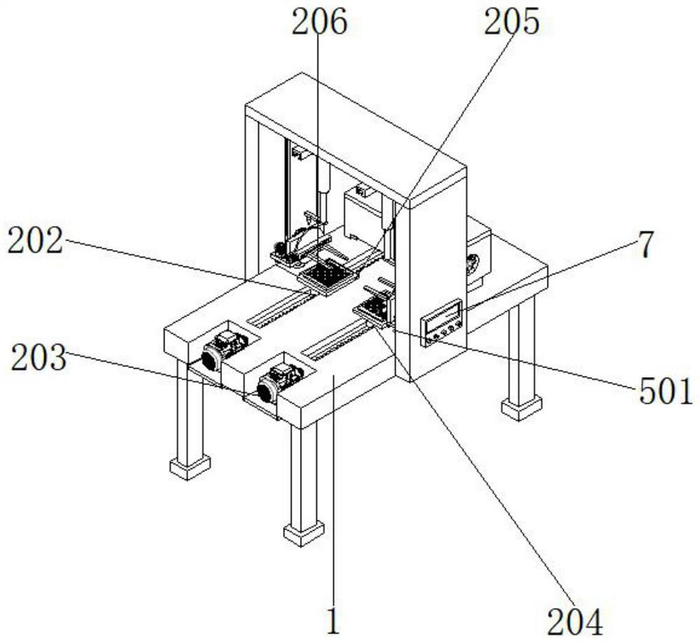
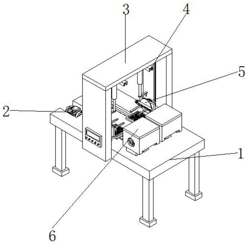
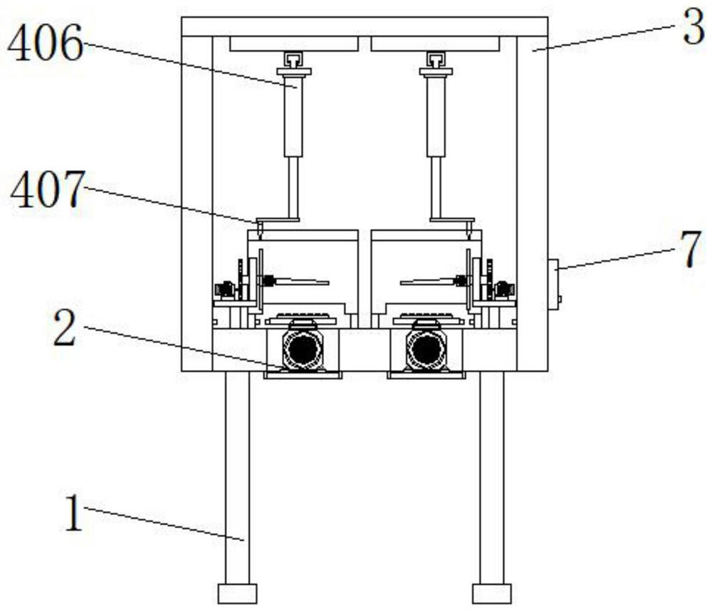
[0034] refer to Figure 1-9 , an installation structure of a double-station flexible welding head mechanism for chip production, including a workbench 1, a conveying assembly 2 is installed on the top of the workbench 1, and the conveying assembly 2 includes a mounting groove 201 opened on the top of the workbench 1 , the inside of the installation groove 201 is installed with a screw rod 202 connected with a bearing, and one end of the screw rod 202 is connected with a first servo motor 203 through a coupling, and the outer wall of the middle part of the screw rod 202 is screwed with a support block 204, and supports The top of the block 204 is welded with a support plate 205, and the inner walls on both sides of the installation groove 201 are opened with limiting grooves along the length direction, and the outer walls on both sides of the supporting block 204 are bonded with limiting blocks. The size of the block is matched, and the limit groove and the limit block form a s...


PUM


Abstract

The invention discloses a mounting structure of a double-station flexible welding head mechanism for chip production, and relates to the technical field of chip production. For solving the existing problems, the mounting structure comprises a workbench, a conveying assembly is mounted at the top of the workbench, and the conveying assembly comprises a mounting groove formed in the top of the workbench; and a lead screw connected with a bearing is installed in the mounting groove, one end of the lead screw is connected with a first servo motor through a coupler, a supporting block is in threaded connection with the outer wall of the middle of the lead screw, a supporting plate is welded to the top of the supporting block, and an anti-skid supporting pad is bonded to the top of the supporting plate. The corresponding clamping assemblies are arranged on the workbench, when a chip is placed on the anti-skid supporting pad to be welded, the clamping assemblies can be used for clamping and fixing the chip, then a rotating disc is driven to turn over the chip, and the other face of the chip can be welded, so the automatic processing capacity of the mechanism is greatly improved.

Description

technical field [0001] The invention relates to the technical field of chip production, in particular to an installation structure of a double-station flexible welding head mechanism for chip production. Background technique [0002] The existing chip welding device is mainly composed of a chip positioning mechanism and a spot welding mechanism, wherein the chip positioning mechanism is used to adjust the chip before packaging to the correct position, so that it is horizontally located directly above the chip slot, but the existing The positioning device can only realize single-station positioning in the process of use, so that the chip can only be carried out individually during the welding process, which will reduce work efficiency, and the spot welding mechanism is used to place the corrected chip downward. Pressing for welding process, but in the process of welding the existing chip, because the chip cannot be turned over after being fixed, in the process of reusing the ...

Claims


Application Information

Patent Timeline
Patent Type & Authority Applications(China)
IPC IPC(8): H01L21/677H01L21/68H01L21/687H01L21/603H01L21/67
CPCH01L24/75H01L2224/7565H01L2224/757H01L2224/75981H01L2224/759H01L2224/755
Inventor 吴超
Owner 恩纳基智能科技无锡有限公司
Why Eureka
Try Eureka