Aerodynamic heat calculation method considering surface quality injection effect

A surface quality and calculation method technology, applied in calculation, computer-aided design, design optimization/simulation, etc., can solve problems such as single consideration of phenomenon, failure to consider the influence of flow viscosity on parallel surfaces, and inaccurate prediction of phenomena, etc.

Active Publication Date: 2021-12-14
CALCULATION AERODYNAMICS INST CHINA AERODYNAMICS RES & DEV CENT
View PDF5 Cites 0 Cited by
  • Summary
  • Abstract
  • Description
  • Claims
  • Application Information

AI Technical Summary

Problems solved by technology

1. Summarize the calculation method of engineering experience. Although the calculation speed is fast, it cannot explore the detailed influence of the surface mass ejection on the hypersonic vehicle on the aerodynamic thermal environment;
2. Only the influence of vertical surface jet flow in hypersonic vehicle surface mass ejection phenomenon is considered, but the influence of parallel surface flow viscosity is not considered;
3. When processing the surface data of the model during the calculation process, only the normal vel

Method used


Image

  • Aerodynamic heat calculation method considering surface quality injection effect
  • Aerodynamic heat calculation method considering surface quality injection effect
  • Aerodynamic heat calculation method considering surface quality injection effect

Examples


Embodiment 1

[0044] Such as Figure 1~Figure 6 As shown, an aerothermal calculation method considering the surface mass ejection effect, including steps:

[0045] S1, obtaining the geometric shape of the hypersonic vehicle;

[0046] S2, meshing the acquired geometric shape of the hypersonic vehicle;

[0047] S3, acquire hypersonic incoming flow velocity data, hypersonic incoming flow temperature data, hypersonic incoming flow density data and hypersonic incoming flow pressure data, and input surface mass ejection gas mass flow rate data and surface mass ejection gas temperature data into the computer processor;

[0048] S4, in the computer processor, based on the data in step S3 and using the surface mass ejection gas constant data to calculate the surface mass ejection gas density data, the surface mass ejection gas velocity data, the surface mass ejection gas pressure data and the surface mass ejection gas data Mass ejection gas temperature data;

[0049] S5, in the computer processo...

Embodiment 2

[0051] On the basis of Embodiment 1, in step S2, the following sub-steps are included: for the combined working conditions of the hypersonic vehicle shape, the hypersonic vehicle is gradually drawn in the order of point-to-line, line-to-surface, and surface-to-body The mesh corresponding to the geometric shape, and then the meshing is completed.

Embodiment 3

[0053] On the basis of Embodiment 1, in step S4, include sub-steps:

[0054] S40, input surface mass injection gas mass flow rate , surface mass injection gas temperature and the surface mass ejection gas constant , and using the hypersonic incoming flow velocity data, hypersonic incoming flow temperature data, hypersonic incoming flow density data and hypersonic incoming flow pressure data obtained in step S3, the first layer of grid points adjacent to the wall is obtained by flow field calculation pressure , the density on the grid points of the first layer near the wall , the normal velocity on the grid point of the first layer near the wall ;

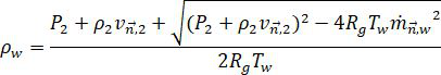
[0055] S41, calculate the surface mass injection gas density data according to the following formula :

[0056]

[0057] S42, using the surface quality ejection gas density data calculated in step S2 and the surface mass injection gas mass flow rate input in step S3 , according to the following formula to calcul...


PUM


Abstract

The invention discloses an aerodynamic heat calculation method considering a surface quality injection effect. The method comprises the following steps: S1, obtaining a geometric shape of a hypersonic aircraft; S2, performing grid division on the obtained geometric shape of the hypersonic aircraft; S3, obtaining hypersonic velocity incoming flow velocity data, hypersonic velocity incoming flow temperature data, hypersonic velocity incoming flow density data and hypersonic velocity incoming flow pressure data, and inputting surface quality injection gas mass flow rate data and surface quality injection gas temperature data into a computer processor; S4, calculating surface mass injection gas density data, surface mass injection gas speed data, surface mass injection gas pressure data and surface mass injection gas temperature data; and S5, calculating wall surface heat flow data of the hypersonic aircraft, and expressing the aerodynamic heat environment of the hypersonic aircraft through the wall surface heat flow data. The aerodynamic thermal environment of the hypersonic aircraft containing surface quality ejection can be predicted more accurately.

Description

technical field [0001] The invention relates to the field of aerodynamic heat and heat protection, and more specifically, relates to an aerodynamic heat calculation method considering the surface mass ejection effect. Background technique [0002] Hypersonic vehicles face a severe aerodynamic thermal environment, and researchers use various thermal protection methods to break through the thermal barrier. Among various thermal protection methods, ablation heat protection technology has been widely used for decades; and sweat cooling technology is expected to solve the thermal protection problem of hypersonic aircraft in adjacent space due to its unique advantages. The above two thermal protection technologies both involve surface mass injection: for example, pyrolysis, evaporation / sublimation and various chemical reactions in the ablation thermal protection technology include the phenomenon of gas precipitation from the surface of the material into the flow field and sweating...

Claims


Application Information

Patent Timeline
IPC IPC(8): G06F30/28G06F30/23G06F30/15G06F113/08G06F119/08G06F119/14
CPCG06F30/28G06F30/23G06F30/15G06F2113/08G06F2119/08G06F2119/14Y02T90/00
Inventor 尤其曾磊杨肖峰李芹刘深深杜雁霞刘磊肖光明魏东桂业伟
Owner CALCULATION AERODYNAMICS INST CHINA AERODYNAMICS RES & DEV CENT
Why Eureka
Try Eureka