
Base station power supply

A base station power supply and control unit technology, applied in the direction of electrical components, adjusting electrical variables, high-efficiency power electronic conversion, etc., can solve problems such as abnormality and output impact of mobile devices connected to the base station power supply

Pending Publication Date: 2021-12-14
LUMLUX CORP
View PDF3 Cites 0 Cited by
  • Summary
  • Abstract
  • Description
  • Claims
  • Application Information

AI Technical Summary

Problems solved by technology

[0004] At present, the base station power supply with multiple outputs cannot realize individual control of each channel. At the same time, when one output is overloaded or damaged, it will affect other outputs, resulting in abnormal mobile devices connected to the base station power supply.

Method used


Image

  • Base station power supply
  • Base station power supply
  • Base station power supply

Examples


Embodiment 1

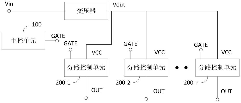
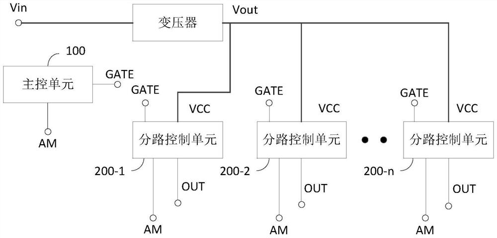
[0032] figure 1 It is a schematic diagram of the structure of the base station power supply in the embodiment, refer to figure 1 , this embodiment proposes a base station power supply, which is configured with a main control unit 100 and several branch control units 200-1-200-n, and the main control unit 100 is respectively connected to the signal terminal GATE of each branch control unit.

[0033] The power input terminal VCC of the branch control unit is used to connect with the output terminal Vout of the internal transformer of the base station power supply, and the power output terminal OUT of the branch control unit is used to connect to the load.

[0034] Exemplarily, in this embodiment, the main control unit 100 is used to control the work of the designated shunt control unit based on manual control instructions, so that the designated shunt control unit connects or disconnects the power path of the load connected to it (the designated load and the power supply path b...

Embodiment 2

[0045] image 3 is a schematic diagram of another base station power supply structure in the embodiment, refer to image 3 , the base station power supply includes a transformer, and the transformer is configured with a filter circuit 1 , a PFC controller 2 , an LLC controller 3 and a synchronous rectification controller 3 .

[0046] Exemplarily, the filter circuit 1 is used for filtering the input voltage of the transformer. As a possible implementation, the filter circuit 1 adopts an EMI filter circuit, and the EMI filter circuit is used for reducing electromagnetic interference of a base station power supply.

[0047] Exemplarily, the EMI filter circuit can be divided into a primary EMI filter circuit and a secondary EMI filter circuit. The primary EMI filter circuit is mainly composed of filter capacitors. The secondary EMI filter circuit is mainly composed of filter capacitors, common-mode inductors, differential-mode inductors, and grounded metal covers.

[0048] Fi...


PUM


Abstract

The invention discloses a base station power supply which is provided with a main control unit and a plurality of branch control units, and the main control unit is connected with the signal end of each branch control unit. The power input end of the shunt control unit is used for being connected with the output end of a transformer in a base station power supply, and the power output end of the shunt control unit is used for being connected with a load. The base station power supply provided by the embodiment of the invention is provided with the main control unit and the plurality of shunt control units, and the isolation between the load and the transformer and between the loads can be realized based on the shunt control units; the fault load can be removed from the transformer power supply network through the control of the main control unit on the shunt control unit corresponding to the fault load or based on the shunt control unit, so that the influence of the fault load on the power supply network is avoided, and the influence on the working states of other normal loads is avoided.

Description

technical field [0001] Embodiments of the present invention relate to power supply technologies, and in particular, to a base station power supply. Background technique [0002] The base station power supply system is the heart of the communication system, and using a stable and reliable base station power supply is the key to ensuring the safe and reliable operation of the communication system. When the power supply network of the communication power supply is abnormal, it is easy to cause the power supply interruption of the communication equipment, so that the communication equipment cannot operate, and then cause the communication circuit to be interrupted and the communication system to be paralyzed, thus causing great economic and social benefit losses. [0003] With the rapid development and wide application of base station power supplies, base station power supplies with multiple outputs have become the mainstream in the market. Based on the base station power suppli...

Claims


Application Information

Patent Timeline
Patent Type & Authority Applications(China)
IPC IPC(8): H02M3/335H02M1/42H02M1/44H02M1/32H02M1/12H02M7/5387
CPCH02M3/33592H02M1/4225H02M1/44H02M1/32H02M1/126H02M7/53871Y02B70/10
Inventor 金宇星邱明丁美林李亨吴典峰
Owner LUMLUX CORP
Learn More