Variable-focal-length cone beam CT device
A cone-beam and focal length technology, applied in radiation detection devices, diagnosis, applications, etc., can solve problems such as poor image quality, large patient radiation, and long time required to achieve the effect of improving imaging quality
- Summary
- Abstract
- Description
- Claims
- Application Information
AI Technical Summary
Problems solved by technology
Method used
Image

Examples
Embodiment 1
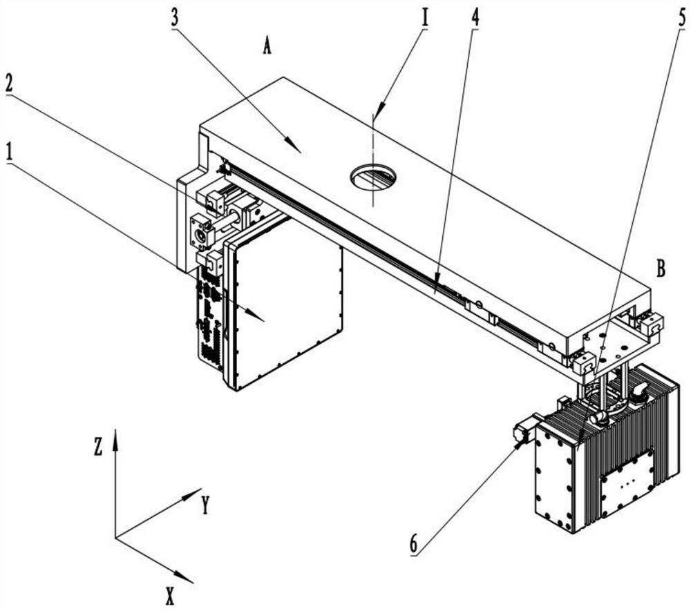
[0034] This embodiment provides a specific implementation of a variable focal length cone beam CT device, such as Figure 1-6 shown, including:
[0035] Detector 1, substrate 3, translation device 4, ray source 5, collimator 6; where:
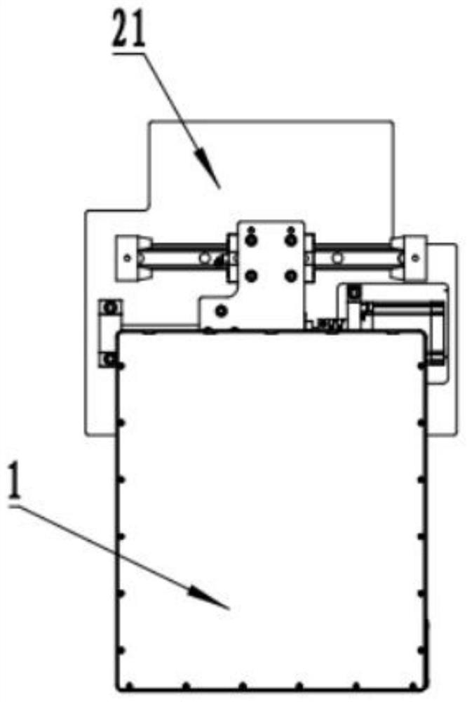
[0036] The detector 1 is arranged at the A end of the substrate 3, the radiation source 5 is arranged at the B end of the substrate 3 through the translation device 4, and the collimator 6 is fixedly arranged at the radiation outlet of the radiation source 5;
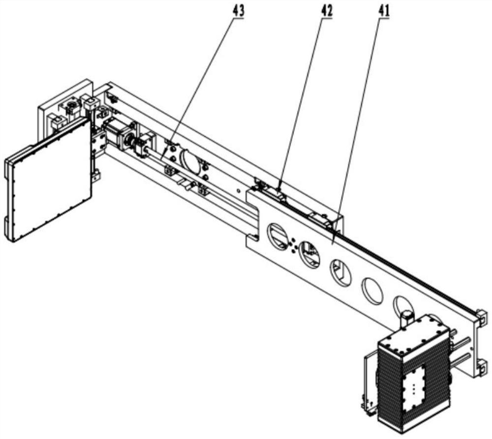
[0037] The translation device 4 is fixed on the bottom of the base plate 3, which includes: a radiation source mounting plate 41, a linear guide device 42, and a linear drive device 43;
[0038] The radiation source 5 is fixedly arranged on the radiation source mounting plate 41 of the translation device 4 , and the linear driving device 43 can drive it to perform translational movement along the linear guide device 42 .
[0039] Further, the linear guide device 42 is arranged along th...
Embodiment 2
[0051] This embodiment provides a specific implementation of a variable focal length cone beam CT device, such as figure 2 As shown, the core components include: a detector 1, a substrate 3, a translation device 4, a radiation source 5, a collimator 6, etc.;
[0052] The detector 1 is located at the A end of the substrate 3 , the radiation source 5 is located at the B end of the substrate 3 through the translation device 4 , and the collimator 6 is fixed at the radiation outlet of the radiation source 5 .
[0053] Further, such as Figure 7 As shown, the translation device 4 is fixed on the base plate 3, which includes: a radiation source mounting plate 41, a linear guide device 42, a linear drive device 43 and other components. refer to Figure 5 , wherein the linear drive device 43 is composed of a linear drive device motor 431, a coupling 432, a screw support seat 433, a linear drive device nut 434, a linear drive device screw rod 435, and the linear drive device nut 434...
PUM
 Abstract
Description
Claims
Application Information
 - R&D Engineer
- R&D Manager
- IP Professional
- Industry Leading Data Capabilities
- Powerful AI technology
- Patent DNA Extraction
Browse by: Latest US Patents, China's latest patents, Technical Efficacy Thesaurus, Application Domain, Technology Topic.
© 2024 PatSnap. All rights reserved.Legal|Privacy policy|Modern Slavery Act Transparency Statement|Sitemap