Clamping unit of automatic dispensing machine

A medicine dispenser, automatic technology, applied in conveyors, conveyor objects, packaging and other directions, can solve the problems of heavy platform weight, drug extrusion, short life and other problems, achieve flexible and free lifting movement, efficient two-way movement, quietness Good results

Active Publication Date: 2021-12-17
江苏芳华智慧医疗科技有限公司
View PDF15 Cites 0 Cited by
  • Summary
  • Abstract
  • Description
  • Claims
  • Application Information

AI Technical Summary

Problems solved by technology

[0005] (1) The existing manipulator adopts the clamping jaw structure, which is not easy to control the clamping force, and it is easy to squeeze the medicine during the grasping of the medicine;
[0006] (2) Due to the structure of screw rod + linear guide rail used for the telescopic and opening and closing actions of the jaws, the cost is high, frequent maintenance is required, the life is short, the noise is large, the platform weight is large, and the power consumption of the motor is large;
[0007] (3) Take and place medicine in one direction, and the rotation of the platform may cause the risk of medicine falling, increasing the overall weight and cost;
[0008] (4) The gripper platform cannot be compatible with different sizes of medicine boxes for temporary storage, which has limitations;

Method used


Image

  • Clamping unit of automatic dispensing machine
  • Clamping unit of automatic dispensing machine
  • Clamping unit of automatic dispensing machine

Examples


Embodiment 1

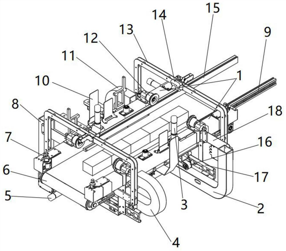
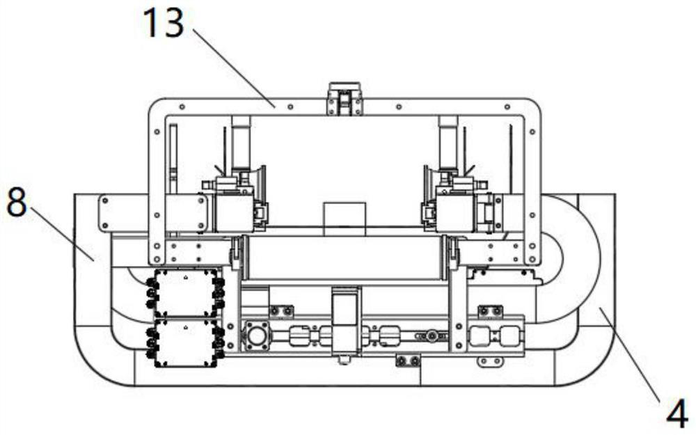
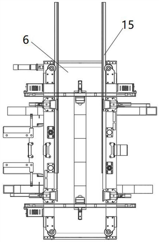
[0040] Embodiment 1, when the medicine is clamped, after the PLC controller receives the instruction, it drives the transmission motor 5 below to rotate, and the transmission motor 5 rotates to drive the transmission wheel to rotate, and the transmission wheel drives the synchronous belt to generate power, so that the synchronous belt drives the synchronous The pulley 16 moves, and the synchronous pulley 16 moves through the support to drive the opening and closing movable beam 1 to move, adjust the opening size of the opening and closing movable beam 1, and the PLC controller controls the micro DC motor 3 on the opening and closing movable beam 1 to work, and the micro The rotation of the DC motor 3 drives the gear to rotate, and the rotation of the gear drives the rack 9 on the two-way telescopic gripper 15 to move, and drives the two-way telescopic gripper 15 to stretch out. The moving beam 1 moves inward to clamp the medicine box, and the micro DC motor 3 drives the two-way...

Embodiment 2

[0042] Embodiment 2, two sets of transmission motors 5 are installed on the supports at both ends respectively. When the medicine is clamped, after the PLC controller receives the instruction, the PLC controller drives the transmission motors 5 at both ends respectively, so that the two ends open. The moving crossbeam 1 forms a certain angle (non-parallel motion), and the PLC controller controls the opening and closing of the moving crossbeam 1. The micro DC motor 3 is energized to work, and the rotation of the micro DC motor 3 drives the gear to rotate, and the gear rotates to drive the two-way telescopic gripper 15 The rack 9 on the top moves, driving the two-way telescopic gripper 15 to stretch out. After the bidirectional telescopic gripper 15 reaches the specified depth of the shelf, the drive motor drives the opening and closing moving beam 1 to move inward to clamp the medicine box, and the micro DC motor 3 drives The two-way telescopic jaw 15 retracts the original posit...


PUM


Abstract

The invention provides a clamping unit of an automatic dispensing machine. The clamping unit comprises a linear sliding rail, opening and closing moving beams, two-way telescopic clamping jaws, micro direct current motors and a two-way belt conveyor, the two sides of the two-way belt conveyor are provided with the opening and closing moving beams, and the two opening and closing moving beams are both installed on supporting pieces; elastic metal connecting plates are arranged between the opening and closing moving beams and the supporting pieces, the opening and closing moving beams can slide along the linear sliding rail through the supporting pieces, the micro direct current motors are installed on the opening and closing moving beams, and the two-way telescopic clamping jaws capable of moving along the opening and closing moving beams are installed in the opening and closing moving beams; and the micro direct current motors drive the two-way telescopic clamping jaws to move along the opening and closing moving beams in a telescopic mode through connecting pieces, and the two-way belt conveyor and the micro direct current motors are connected with a PLC. The clamping unit can grab one or more packages even cylindrical packages on the two sides of a medicine cabinet, the clamping jaws do not need to be rotated, the risk that medicine falls off is eliminated, and the clamping unit is low in cost, light in weight, free of maintenance and simple.

Description

technical field [0001] The invention relates to the technical field of sewage treatment, in particular to a clamping unit of an automatic medicine dispensing machine. Background technique [0002] At present, the dispensing of medicines in the central pharmacies of most hospitals relies mostly on manual operations; pharmacists take the medicines and distribute the medicines corresponding to the patients to the patients. [0003] Manual dispensing errors will occur, which will bring unnecessary troubles to patients and hospitals, and even damage the health of patients. When the number of people taking medicine is large, the pharmacist is too busy at all, and the patients can only wait in line, which delays the time of the patients, and it is even more torture for some patients with limited mobility. [0004] When utilizing manipulator to take medicine, there is following defect: [0005] (1) The existing manipulator adopts the clamping jaw structure, which is not easy to co...

Claims


Application Information

Patent Timeline
Patent Type & Authority Applications(China)
IPC IPC(8): B65G47/90A47F1/04
CPCB65G47/90B65G47/905A47F1/04B65G2207/08B65G2201/025
Inventor 陈磊何凤雷
Owner 江苏芳华智慧医疗科技有限公司
Why Eureka
Try Eureka