A lamination dryer for high-strength interior wall panels

An interior wall panel and high-strength technology, which is applied in the direction of dryers, drying, local mixing dryers, etc., can solve the problems of manual feeding, poor drying efficiency, and high labor intensity, and achieve convenient feeding operations , high level of automation, and the effect of improving drying efficiency

Active Publication Date: 2022-08-02
江苏文泰节能新材料有限公司
View PDF5 Cites 0 Cited by
  • Summary
  • Abstract
  • Description
  • Claims
  • Application Information

AI Technical Summary

Problems solved by technology

[0004] The object of the present invention is to provide a laminated dryer for high-strength interior wallboards, which solves the problem that the existing dryer needs manual feeding when laminating and drying the interior wallboards. Then through manual unloading, the labor intensity is too large, and the drying efficiency is poor to meet the actual use needs

Method used


Image

  • A lamination dryer for high-strength interior wall panels
  • A lamination dryer for high-strength interior wall panels
  • A lamination dryer for high-strength interior wall panels

Examples


Embodiment 2

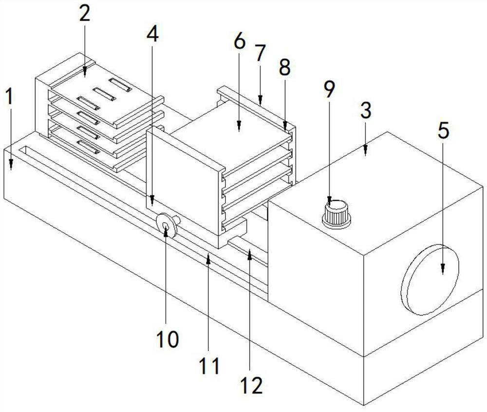
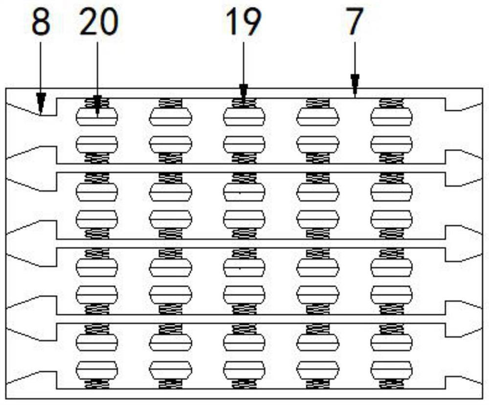
[0034] further improved, such as Image 6Shown: the side wall of the drying box 3 and the opposite surface of the clamping mechanism are provided with openings, the interior of the drying box 3 is symmetrically provided with several groups of pressing plates 34 and each group is provided with two respectively, and the two pressing plates 34 are arranged between them. A squeeze cavity 35 is respectively formed between the two ends of the squeeze plate 34. The two ends of the squeeze plate 34 are respectively provided with connecting plates 31 and the surface of the connecting plates 31 is provided with threaded holes. The interior of the drying box 3 is symmetrical and vertically arranged with a transmission shaft 33. The transmission shaft Several groups of threaded structures 36 are symmetrically arranged on the surface of 33 and are connected to the threaded holes through the threaded structures 36 . A motor one 9 is installed on the top side of the drying box 3, and the pow...

Embodiment 3

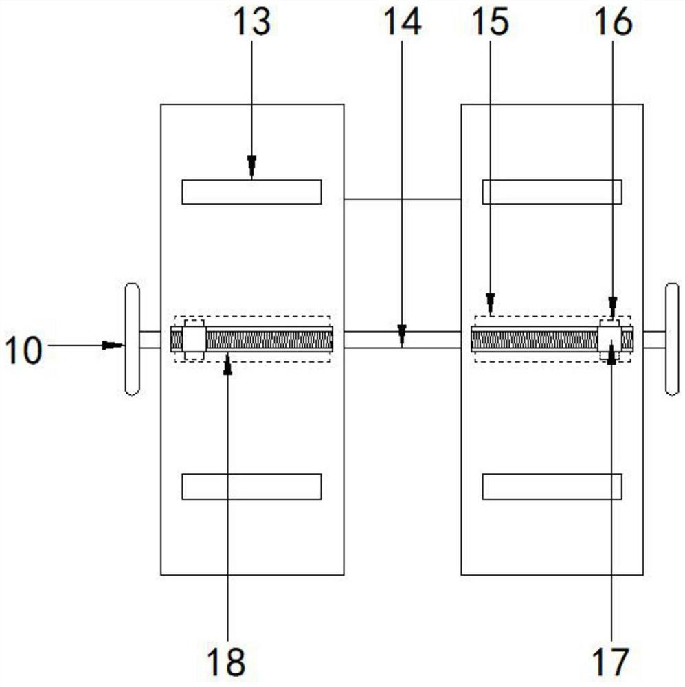
[0036] further improved, such as Figure 5 Shown: the auxiliary mechanism includes a motor two 26, a sprocket one 27, a transmission wheel 30 and an auxiliary roller 25, the surface of the support plate 23 is provided with a mounting groove 24, and the two ends of the auxiliary roller 25 are respectively installed with connecting shafts 28 and The connecting shaft 28 is rotatably connected with the support plate 23, and the end of the connecting shaft 28 extends to the fixed block 22 and is connected to the first sprocket 27. The horizontally arranged sprockets 27 are connected by a chain, and the end of the connecting shaft 28 in the middle is also A drive wheel 30 is installed, which is connected by a chain 29, and the auxiliary roller 25 is driven to rotate by a motor, which is convenient to push the wall plate 6 on the pallet 23 during the process of loading and unloading, and improves the speed of loading and unloading.

[0037] When the present invention is in use, a cla...


PUM


Abstract

The invention discloses a laminated dryer for high-strength interior wall panels, comprising: a base, a feeding mechanism, a drying box and a clamping mechanism, wherein the feeding mechanism, the drying box and the clamping mechanism are all mounted on the base, And the feeding mechanism and the clamping mechanism are installed on the top two ends of the base, and the drying box is installed between the feeding mechanism and the clamping mechanism; The bottom of the sliding rail is fixedly connected with the base and the end of the sliding rail extends to the inside of the drying box. The present invention is provided with a clamping mechanism and a feeding mechanism. By placing the inner wall panel on the pallet, and then moving the clamping mechanism to the direction of the feeding mechanism, the inner wall panel is embedded in the clamping groove of the clamping mechanism, and passes through the inner wall of the clamping groove. The clamping block is used to clamp the wall panel, and then the feeding mechanism moves down, so that the horizontal height of the wall panel is higher than the upper end of the baffle, and then the clamping mechanism is reset to complete the feeding operation. The feeding operation is convenient and the automation level is high.

Description

technical field [0001] The invention relates to the technical field of drying of interior wall panels, and more particularly relates to a laminated dryer for high-strength interior wall panels. Background technique [0002] The dryer has several modes such as belt drying, tumble drying, box drying, tower drying, etc. The heat source includes coal, electricity, gas, etc.; materials in the drying process have hot air flow type and radiation type, etc. , Hot air tumble drying is that the hot air moves forward from the tail, fully contacts the material, and makes full use of the heat transfer through heat conduction, convection and radiation; the heat energy is directly transferred to the material, so that the moisture of the material is continuously evaporated in the cylinder, and the material is fed. The air induction device at the mouth draws out a large amount of water and wet air to prevent secondary pollution caused by dust discharge; through the internal spiral stirring, ...

Claims


Application Information

Patent Timeline
Patent Type & Authority Patents(China)
IPC IPC(8): F26B9/06F26B9/04F26B21/00F26B25/00F26B25/02F26B25/18
CPCF26B9/066F26B9/04F26B21/001F26B21/004F26B25/003F26B25/02F26B25/18
Inventor 张宇
Owner 江苏文泰节能新材料有限公司
Why Eureka
Try Eureka