Eddy current thermal imaging defect reconstruction method based on electrical impedance tomography

A technology of electrical impedance imaging and thermal imaging, which is applied in the field of defect detection, can solve the problem that it is difficult to obtain the true shape of defects

Active Publication Date: 2021-12-17
UNIV OF ELECTRONICS SCI & TECH OF CHINA
View PDF7 Cites 1 Cited by
  • Summary
  • Abstract
  • Description
  • Claims
  • Application Information

AI Technical Summary

Problems solved by technology

However, the high-temperature region only exists at both ends of th

Method used


Image

  • Eddy current thermal imaging defect reconstruction method based on electrical impedance tomography
  • Eddy current thermal imaging defect reconstruction method based on electrical impedance tomography
  • Eddy current thermal imaging defect reconstruction method based on electrical impedance tomography

Examples


Embodiment

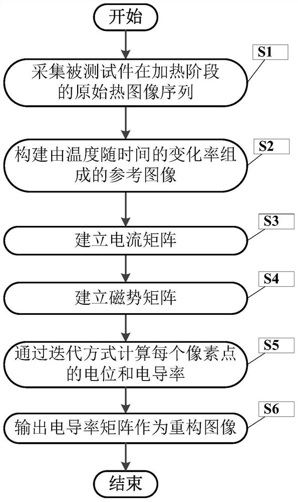
[0066] figure 1 It is a flowchart of a defect reconstruction method based on electrical impedance imaging in eddy current thermal imaging according to the present invention.

[0067] In this example, if figure 1 As shown, the present invention is based on electrical impedance imaging eddy current thermal imaging defect reconstruction method, comprising the following steps:

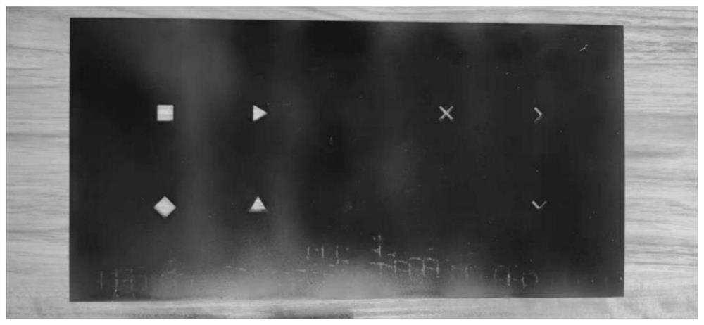
[0068] S1. Use a coil to excite the test piece. The coil is a high-conductivity hollow copper tube with an inner diameter of 6.35mm, and a current with a frequency of 275kHz and an amplitude of 150A is passed through. The tested piece is austenitic 304 stainless steel with a thickness of 0.28mm. Defects of different shapes are engraved, such as figure 2 shown. The coil is placed horizontally on the surface of the test piece, and the lifting distance from the test piece is 1cm. When the current is passed through the coil, heating starts, and the heating time is 200ms. Use an infrared thermal imager to...


PUM


Abstract

The invention discloses an eddy current thermal imaging defect reconstruction method based on electrical impedance tomography. The method comprises the following steps of firstly, acquiring a thermal image sequence in a heating stage, performing curve fitting on pixel points in the thermal image sequence to obtain a reference image of which the temperature is changed along with time, then extracting a current matrix and a magnetic potential matrix from the reference image, and acquiring conductivity distribution meeting conditions according to an iterative formula so as to obtain a reconstructed image representing the defect and realize identification of the shape of the defect.

Description

technical field [0001] The invention belongs to the technical field of defect detection, and more specifically relates to an eddy current thermal imaging defect reconstruction method based on electrical impedance imaging. Background technique [0002] The eddy current thermal imaging detection method is widely used in the field of non-destructive testing of metal materials due to its advantages of non-contact, large detection range and high detection efficiency. The coil with high-frequency alternating current induces eddy current in the conductor specimen, and the heating process and cooling process of the specimen surface are recorded by an infrared thermal imager. Current concentration is formed in the defective area to generate a high-temperature zone, and the location of the defect is detected through the high-temperature zone. [0003] However, this method can only identify the defect location, and it is difficult to quantitatively evaluate the defect shape. In aeros...

Claims


Application Information

Patent Timeline
IPC IPC(8): G01N25/72G01N27/90G01N27/04
CPCG01N25/72G01N27/90G01N27/9046G01N27/041G01N1/44G01N27/9006
Inventor 白利兵张旭任超梁一平张睿恒段勇邵晋梁郑亚莉程玉华
Owner UNIV OF ELECTRONICS SCI & TECH OF CHINA
Why Eureka
Try Eureka