

Nasal laryngoscope with injection administration function and convenient angle adjustment function
A technology for adjusting the angle and rhinolaryngoscope, applied in the field of rhinolaryngoscope, can solve the problems of unstable force, free adjustment, inconvenient support frame, etc., and achieve good coverage
- Summary
- Abstract
- Description
- Claims
- Application Information
AI Technical Summary
Problems solved by technology
Method used
Image

Examples
Embodiment 1
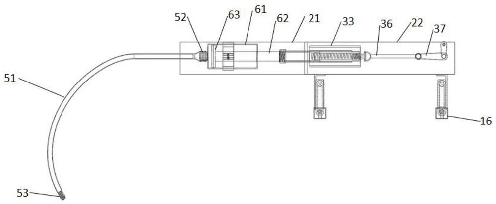
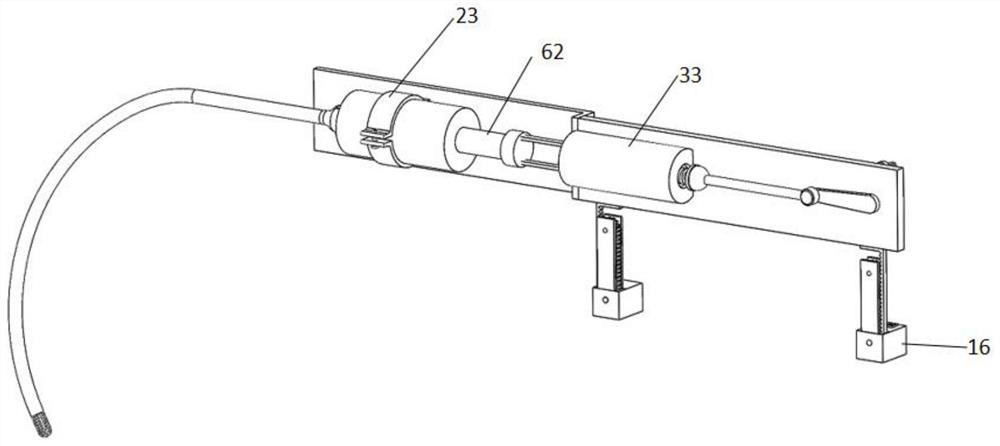
[0048] Please refer to Figure 1-Figure 5 , Figure 7-Figure 9 , Figure 13 , a nasal laryngoscope with injection function and convenient angle adjustment in this embodiment, which includes a nasal laryngoscope body and an injection structure, the nose laryngoscope body and the injection structure are flexibly connected; the outside of the injection structure is used to support the injection The supporting structure of the structure, and the operating structure for controlling the injection or suction operation of the injection structure; the operating structure is arranged on the first face and / or the second face of the supporting structure; the lower end of the supporting structure is arranged for adjusting the position of the supporting structure and the injecting structure The control structure of height and inclination angle; the control structure includes: the adjustment plate 11 arranged at the lower end of the support structure, the rack belt 12 that moves relative to...
Embodiment 2
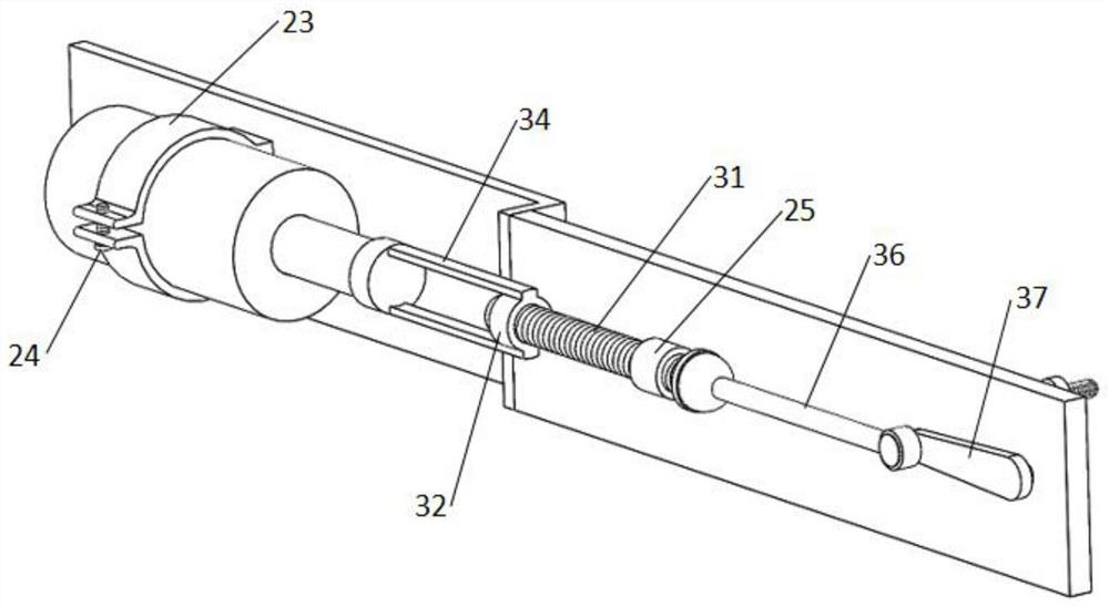
[0065] Please refer to Figure 6 The difference between this embodiment and the other embodiments is the connection between the injection structure and the operation structure. Specifically, the integral connection between the connecting rod 34 and the injection structure in Embodiment 1 is modified to the following technical features: the connection assembly also includes a The connecting rod one 34 is away from the connecting cap 35 at one end of the threaded outer sleeve 32, and the connecting cap 35 is movably connected with the injection structure; after connecting the connecting cap 35 and the injection structure during use, the operating structure is operated. Concrete use method is identical with embodiment 1.
Embodiment 3
[0067] Please refer to Figure 10-Figure 13 The difference between this embodiment and Embodiment 1 or 2 is that the operating components are different. The specific technical features are: the operating component includes an operating rod-36 that is movably connected with the threaded rod-31, and an operation that is movably connected with the operating rod-36. Lever two 37, operating lever three 38 integrally connected with operating lever two 37, and a rotary control member 311 connected with operating lever three 38; operating lever two 37 and operating lever three 38 are perpendicular to each other; operate the rotary control member in this way 311, sequentially drives the operating rod three 38 and the operating rod two 37 to rotate, and now the position of the operating rod one 36 will change with the rotation of the operating rod two 37, and the operating rod one 36 surrounds the operating rod one 36 and the threaded rod The connection point of one 31 rotates, thereby ...
PUM
 Abstract
Description
Claims
Application Information