Plasma arc welding machine

A plasma arc and welding machine technology, applied in the field of metal welding, can solve the problems of reducing the connection between the metal and the welding connection block, debris easily falling on the welding position, affecting the welding efficiency, etc., so as to avoid repeated welding or omission, reduce Welding is not tight and reduces labor intensity

Pending Publication Date: 2021-12-24
任伟
View PDF8 Cites 1 Cited by
  • Summary
  • Abstract
  • Description
  • Claims
  • Application Information

AI Technical Summary

Problems solved by technology

[0006] Aiming at the deficiencies of the prior art, the present invention provides a plasma arc welding machine, which solves the problem that there is a certain center position difference between the welding connection block and the metal, and welding offset occurs, which affects the welding efficiency, and the welding process occurs Debris tends to settle at the weld location, reducing the connection between the metal and the welded joint

Method used


Image

  • Plasma arc welding machine
  • Plasma arc welding machine
  • Plasma arc welding machine

Examples


Embodiment 1

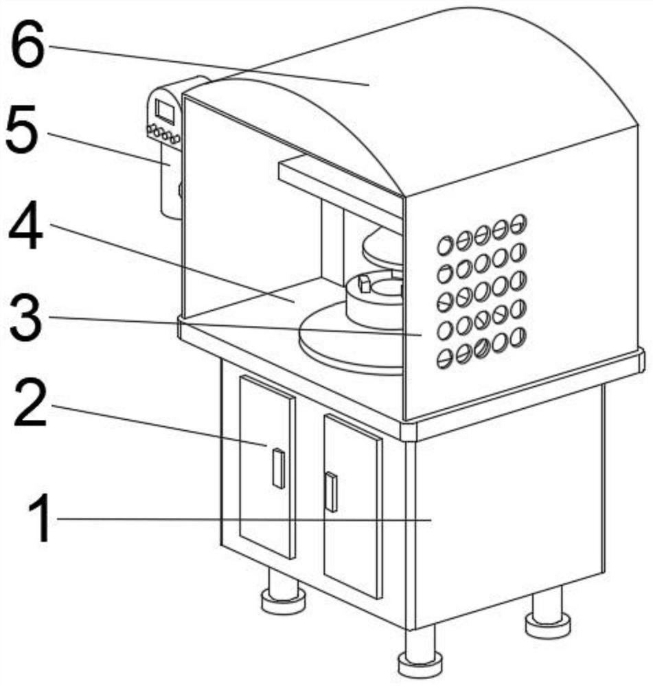
[0033] see Figure 1-2 , the present invention provides a technical solution: a plasma arc welding machine, comprising a main body box 1, maintenance box doors 2 are arranged on both sides of the front middle part of the main body box 1, and a welding device 4 is fixedly connected to the top of the main body box 1, and the welding device Both sides of the top of 4 are fixedly connected with protective plate 3, the middle part of the right outer wall of protective plate 3 is fixedly connected with controller 5, and the top of protective plate 3 is fixedly connected with collection box 6.

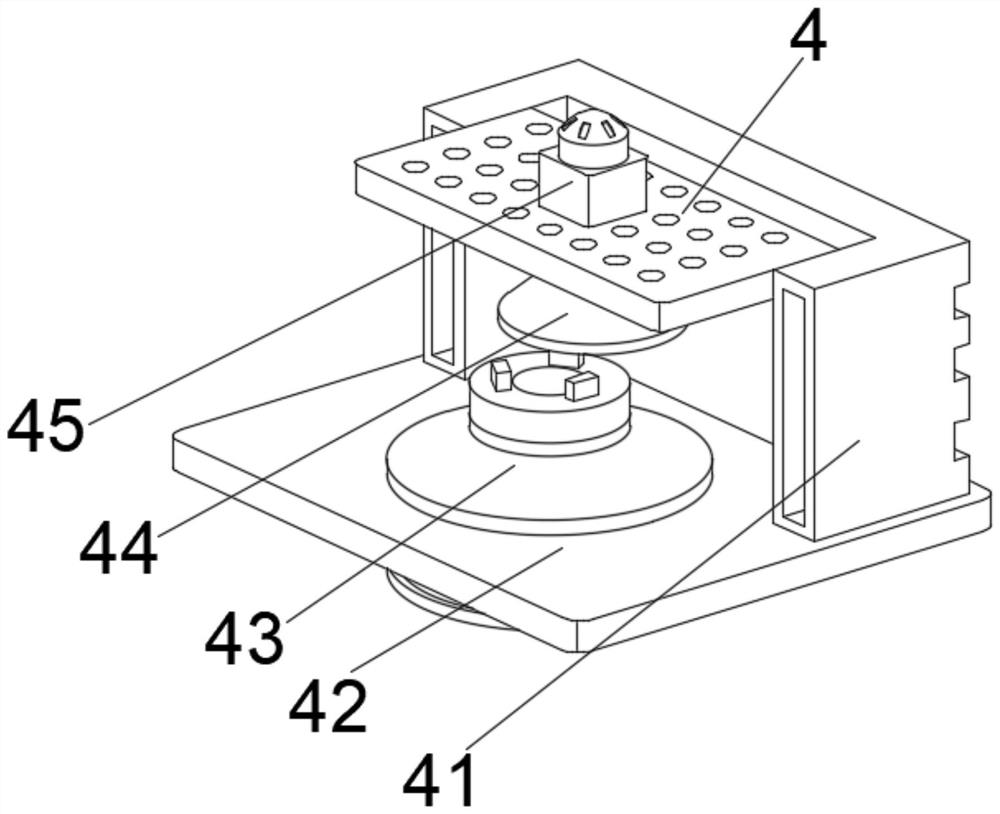
[0034] Wherein, welding device 4 comprises working platform 42, and the top middle position of working platform 42 is provided with fastening mechanism 43, and the top of working platform 42 is positioned at the both sides of fastening mechanism 43 and is fixedly connected with support frame 41, and the top center of support frame 41 A plasma welder 45 is provided at the position, and the bot...

Embodiment 2

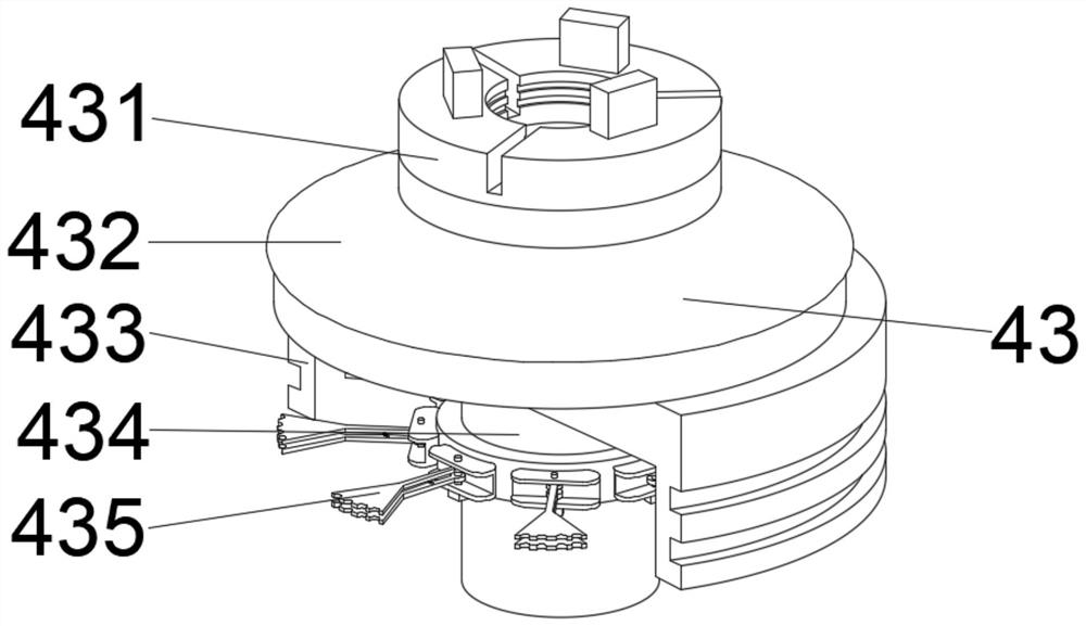
[0037] see Figure 1-4 On the basis of Embodiment 1, the present invention provides a technical solution: component 1 of the fastening mechanism 43 includes a connecting shell 433, the top of the connecting shell 433 is fixedly connected with a stabilizing block 432, and the top middle position of the stabilizing block 432 is provided with For the fastener 431 , a guide post 434 is provided at the middle of the inner cavity top of the connection shell 433 , and a positioning fastening body 435 is provided at the middle outer surface of the guide post 434 .

[0038] Wherein, the first component of the protection mechanism 44 includes a protective case 441, the top of the protective case 441 is fixedly connected with a connector 443, the middle part of the outer wall on both sides of the protective case 441 is fixedly connected with a fixing seat 445, and the bottom of the inner wall on both sides of the protective case 441 is provided with The transition ring 442 and the middle...

Embodiment 3

[0041] see Figure 1-6 , on the basis of Embodiment 1 and Embodiment 2, the present invention provides a technical solution: the second component of the fastening mechanism 43 includes a rotating part d2, the top of the rotating part d2 is provided with a contact body d1, and the inner cavity of the rotating part d2 There is a rubber guide piece d3 in the middle of the top, positioning columns d5 are fixedly connected to both sides of the front of the rotating piece d2, and a friction increasing block d4 is arranged in the middle of the back of the rotating piece d2, and the front of the friction increasing piece d4 runs through the rotating piece d2 and extends to The inside of the rotating part d2.

[0042] Among them, the second component of the protection mechanism 44 includes a fixed connector t1, the top of the inner wall on both sides of the fixed connector t1 is fixedly connected with the limit block t2, and the middle part of the outer wall on both sides of the fixed ...


PUM


Abstract

The invention discloses a plasma arc welding machine which comprises a main body box. Maintenance box doors are arranged on the two sides of the middle of the front face of the main body box, a welding device is fixedly connected to the top of the main body box, protection plates are fixedly connected to the two sides of the top of the welding device, a controller is fixedly connected to the middle of the outer wall of the right side of each protection plate, and the top of each protection plate is fixedly connected with a collection box. The plasma arc welding machine provided by the invention relates to the technical field of metal welding. According to the plasma arc welding machine, the situation that chippings splash everywhere on a working platform is prevented; the arranged plasma welding machine can move along with a vertical supporting frame, so that the situation that welding positioning deviates is avoided; the device can be separated through the supporting frame, so that the phenomenon that cleaning is not thorough due to the fact that the chippings splash everywhere during welding is prevented; and sparks generated during welding can be blocked through a protection mechanism, so that the influence of the sparks on workers is effectively reduced, and the labor intensity of the workers is conveniently reduced.

Description

technical field [0001] The invention relates to the technical field of metal welding, in particular to a plasma arc welding machine. Background technique [0002] Plasma arc welding refers to the fusion welding method that uses the high energy density beam of plasma arc as the welding heat source. Plasma arc welding has the advantages of energy concentration, high productivity, fast welding speed, small stress and deformation, stable arc and is suitable for welding thin plates and boxes. And other characteristics, especially suitable for welding of various refractory, easily oxidized and heat-sensitive metal materials (such as tungsten, molybdenum, copper, nickel, titanium, etc.). [0003] According to Chinese Patent No. CN110883452A, a kind of welding equipment for metal product processing disclosed by the provided chute facilitates the placement plate to slide to the other side inside the chute through the slider. When sliding to a suitable position, release the button so ...

Claims


Application Information

Patent Timeline
IPC IPC(8): B23K10/02B23K37/00B23K37/04B23K37/047
CPCB23K10/02B23K37/00B23K37/0435B23K37/047
Inventor 任伟
Owner 任伟
Why Eureka
Try Eureka