Automatic putting device for mechanical parts

A technology of mechanical parts and delivery devices, which is applied in the direction of conveyor objects, packaging, loading/unloading, etc., can solve the problems of increasing the manufacturing cost of automatic delivery structures, many electronic components and transmission structures, and increasing the probability of device failure, etc., to achieve increased Large elasticity, low maintenance difficulty, and the effect of reducing production costs

Active Publication Date: 2021-12-24
JILIN TEACHERS INST OF ENG & TECH
View PDF11 Cites 2 Cited by
  • Summary
  • Abstract
  • Description
  • Claims
  • Application Information

AI Technical Summary

Problems solved by technology

[0003] In order to meet the needs of automatic processing of mechanical parts, those skilled in the art have made various designs for the automatic delivery structure of mechanical parts. However, the existing design structures are relatively complicated, and many electronic components and transmission structures are used. The manufacturing cost of the automatic delivery structure also increases the difficulty of maintenance and increases the failure probability of the device

Method used


Image

  • Automatic putting device for mechanical parts
  • Automatic putting device for mechanical parts
  • Automatic putting device for mechanical parts

Examples


Embodiment Construction

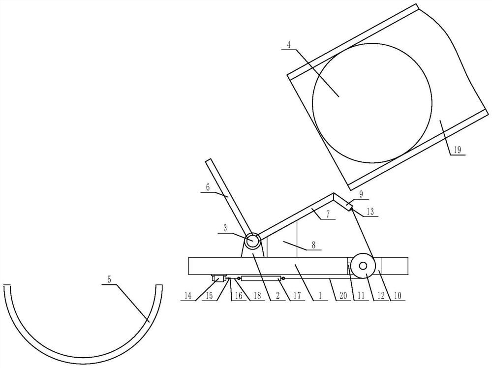
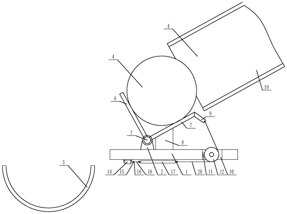
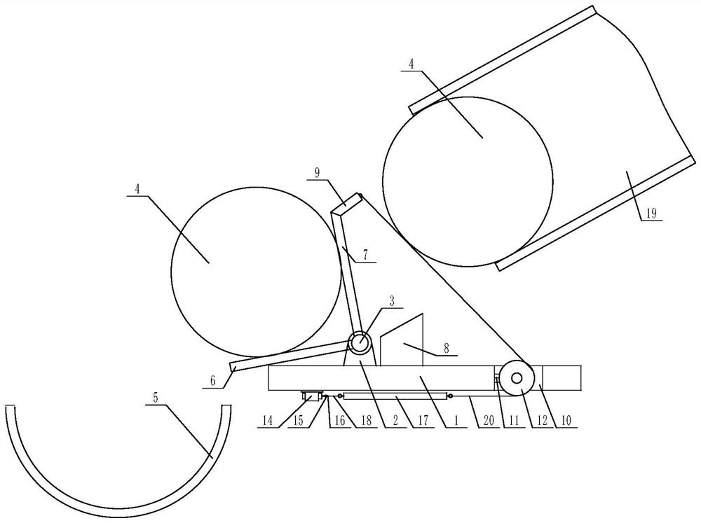
[0026] The present invention is specifically described below in conjunction with accompanying drawing, as Figure 1-5 shown;

[0027] The inventive point of the present application is that the limit plate one 6 and the limit plate two 7 are fixedly installed on the rotating shaft, the length direction of the limit plate one and the limit plate two is the same, the limit plate one and the limit plate The angle between the two is greater than sixty degrees and less than one hundred and twenty degrees. The length of the first limit plate is the same as that of the second limit plate and matches the length of the rotating shaft. The first limit plate and the limit plate Plate two can follow the rotation of the shaft, and the upper surface of the base plate is fixedly installed with a block 8, which is located between the feeding channels of the shaft. The shape of the block is a right-angled trapezoid, and the slope of the block faces Above, the slope of the stopper is low on the...


PUM


Abstract

The invention discloses an automatic putting device for mechanical parts. The automatic putting device comprises a bottom plate, two supporting plates are fixedly installed on the upper surface of the bottom plate, a rotating shaft is installed on the two supporting plates, a discharging channel is formed in the upper right portion of the bottom plate, mechanical parts are installed in the discharging channel, and a port of the discharging channel obliquely points to the rotating shaft downwards. A feeding channel is arranged on the lower left portion of the bottom plate, the feeding channel obliquely downwards points to a workbench, a first limiting plate and a second limiting plate are fixedly installed on the rotating shaft, a check block is fixedly installed on the upper surface of the bottom plate and located between discharging channels of the rotating shaft, and the weight of the second limiting plate is larger than that of the first limiting plate. The device has the beneficial effects of being reasonable in structural design, low in working energy consumption and high in practicability.

Description

technical field [0001] The invention relates to the technical field of mechanical automatic processing, in particular to an automatic feeding device for mechanical parts. Background technique [0002] With the continuous development of science and technology, the market puts forward higher and higher requirements for automation technology, and also provides necessary conditions for the innovation of automation technology. Automation technology is widely used in industry, agriculture, military, scientific research, transportation, commerce, medical care, services and households. Especially in the process of mechanical processing, the use of automation technology can not only liberate people from heavy physical labor, some mental work, and harsh and dangerous working environments, but also greatly improve labor productivity. [0003] In order to meet the needs of automatic processing of mechanical parts, those skilled in the art have made various designs for the automatic del...

Claims


Application Information

Patent Timeline
Patent Type & Authority Applications(China)
IPC IPC(8): B65G65/23B65G47/04B65G47/57B65G47/82
CPCB65G65/23B65G47/57B65G47/82B65G47/04
Inventor 罗忠宝
Owner JILIN TEACHERS INST OF ENG & TECH
Why Eureka
Try Eureka