Environment-friendly industrial sewage rapid acidification treatment device

A technology for industrial sewage and acidification treatment, applied in anaerobic digestion treatment, grain treatment and other directions, can solve the problems of inability to stir, discharge sewage can not be evenly discharged, and the overall treatment effect is not very good, and achieves convenient and economical manual operation. human effect

Pending Publication Date: 2021-12-24
陈水美
View PDF0 Cites 0 Cited by
  • Summary
  • Abstract
  • Description
  • Claims
  • Application Information

AI Technical Summary

Problems solved by technology

[0005] In order to overcome the above-mentioned method, the sludge in the hydrolysis acidification tank cannot be stirred during operation, and the sewage cannot be discharged uniformly, so that the overall treatment effect is not very good. The technical problem to be solved by the present invention is to provide An environmentally friendly industrial sewage rapid acidification treatment device that can discharge sewage evenly and stir the sludge in the hydrolysis acidification tank, thereby improving the overall treatment effect

Method used


Image

  • Environment-friendly industrial sewage rapid acidification treatment device
  • Environment-friendly industrial sewage rapid acidification treatment device
  • Environment-friendly industrial sewage rapid acidification treatment device

Examples


Embodiment 1

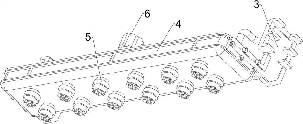
[0042] An environmentally friendly industrial sewage rapid acidification treatment device, such as Figure 1-8 As shown, it includes a first mounting seat 1, a rodless cylinder 2, a connecting frame 3, a first water tank 4, a spray head 5, a first connecting pipe 6, a water pump 7, a communication pipe 8, a sliding assembly 9 and a rotating assembly 10. A rodless cylinder 2 is installed on the top, front and rear sides of a mounting seat 1, a connecting frame 3 is connected between the piston parts of the rodless cylinder 2 on both sides, and a first water tank 4 is connected to the lower part of the connecting frame 3, and the bottom of the first water tank 4 The left and right sides are connected with a plurality of nozzles 5 at even intervals. The nozzles 5 are used to spray out sewage. The nozzles 5 on both sides are symmetrically arranged. The top of the first water tank 4 is connected with a first connecting pipe 6 in the middle. A water pump 7 is installed in the middle...

Embodiment 2

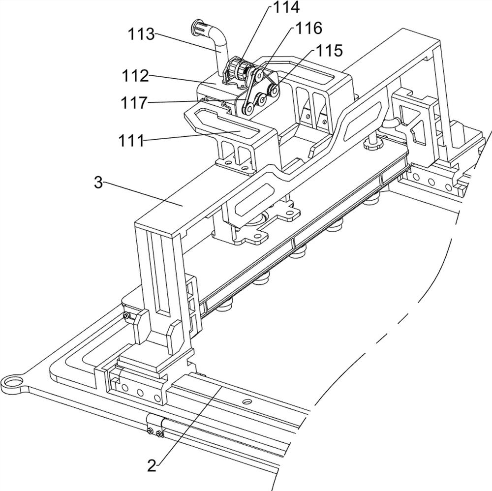
[0048] On the basis of Example 1, as figure 1 , 9 , Figure 10 , Figure 11 , Figure 12 and Figure 13 As shown, it also includes a crushing component 11, which is used to crush the agglomerated impurities doped in the sewage, and the crushing component 11 includes a second mounting seat 111, a second water tank 112, a second connection The pipe 113, the drive motor 114, the toothed roller 115, the first pulley 116 and the first flat belt 117, the top of the connecting frame 3 is connected with a second mounting seat 111, the second mounting seat 111 is connected with a second water tank 112, and the communication pipe 8 Connected to the second water tank 112, the communication pipe 8 is communicated with the inside of the second water tank 112, the top of the second water tank 112 is connected with a second connecting pipe 113, the top of the second water tank 112 is installed with a driving motor 114, and the driving motor 114 is located in the second connecting pipe O...

Embodiment 3

[0053] On the basis of Example 2, as figure 1 , Figure 14 , Figure 15 , Figure 16 and Figure 17 As shown, a blocking component 13 is also included, and the blocking component 13 is used to block the nozzle 5. The blocking component 13 includes a connecting frame 131, a support plate 132 and a rubber plate 133. The top left side of the first mounting seat 1 is connected with a The connection frame 131 is connected with a support plate 132 , the top of the support plate 132 is connected with a rubber plate 133 , and the top of the rubber plate 133 is in contact with the bottom of the nozzle 5 .

[0054] In the initial state, the rubber plate 133 can block the bottom of the spray head 5 to prevent the spray head 5 from spraying water. When the spray head 5 is no longer in contact with the rubber plate 133, the spray head 5 can spray water, thereby preventing the spray head 5 from spraying water. When the sewage is sprayed, the sewage is sprayed on the edge of the hydrolys...


PUM


Abstract

The invention relates to an acidification treatment device, in particular to an environment-friendly industrial sewage rapid acidification treatment device. The invention provides the environment-friendly industrial sewage rapid acidification treatment device which can uniformly discharge sewage and can stir sludge in the hydrolysis acidification pool so as to improve the overall treatment effect. The environment-friendly industrial sewage rapid acidification treatment device comprises a first mounting seat, a connecting frame, a first water tank and nozzles, wherein rodless cylinders are mounted on the two sides of the top of the first mounting seat; the connecting frame is connected between the piston parts of the rodless cylinders on the two sides; the lower part in the connecting frame is connected with the first water tank through which sewage passes; the two sides of the bottom of the first water tank are evenly connected with the multiple nozzles used for discharging sewage at intervals, and the nozzles on the two sides are symmetrically arranged. The sewage is sprayed into the hydrolysis acidification pool through the nozzle, so that the effect of treating the sewage is realized.

Description

technical field [0001] The invention relates to an acidification treatment device, in particular to an environment-friendly industrial sewage rapid acidification treatment device. Background technique [0002] Sewage treatment is the most important link in environmental protection. In the process of sewage treatment, it is usually treated by hydrolysis and acidification. At present, the way of hydrolysis and acidification treatment is usually to directly discharge the sewage into the hydrolysis acidification tank, so as to treat the sewage. The above method cannot stir the sludge in the hydrolysis acidification tank during operation, and does not discharge the sewage. It can be discharged evenly, the reaction speed is low during treatment, and the acidification treatment is not complete enough, which easily makes the overall acidification treatment effect not very good and cannot meet people's needs. [0003] Therefore, it is necessary to develop an environment-friendly ind...

Claims


Application Information

Patent Timeline
IPC IPC(8): C02F3/28B02C4/08B02C4/42
CPCC02F3/28B02C4/08B02C4/42B02C2201/063
Inventor 陈水美
Owner 陈水美
Why Eureka
Try Eureka