
Hydrodynamic journal bearing

A hydrostatic bearing and liquid technology, which is applied in the field of hydrostatic bearings, can solve problems such as the failure of bearings to work normally, and achieve the effects of improving the stability of movement, simple device structure, and convenient operation

Pending Publication Date: 2021-12-24
JIANGSU JITRI JINGKAI HIGH VALUE MFG CO LTD
View PDF7 Cites 4 Cited by
  • Summary
  • Abstract
  • Description
  • Claims
  • Application Information

AI Technical Summary

Problems solved by technology

In actual production, due to the different types of workpieces and processing requirements, it is necessary for the bearing to be able to change within a large speed range, and to ensure the rotation accuracy and stability of the main shaft. The gap has been fixed when leaving the factory. Such a hydrostatic bearing can only work in a small speed range. The change of the spindle speed will change the formation conditions of the oil film, and the bearing will not work normally. It is difficult to adapt different working conditions

Method used


Image

  • Hydrodynamic journal bearing
  • Hydrodynamic journal bearing
  • Hydrodynamic journal bearing

Examples


Embodiment

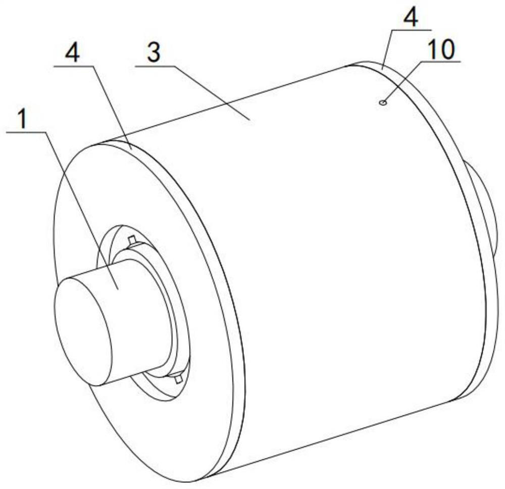
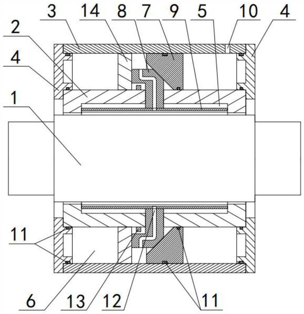
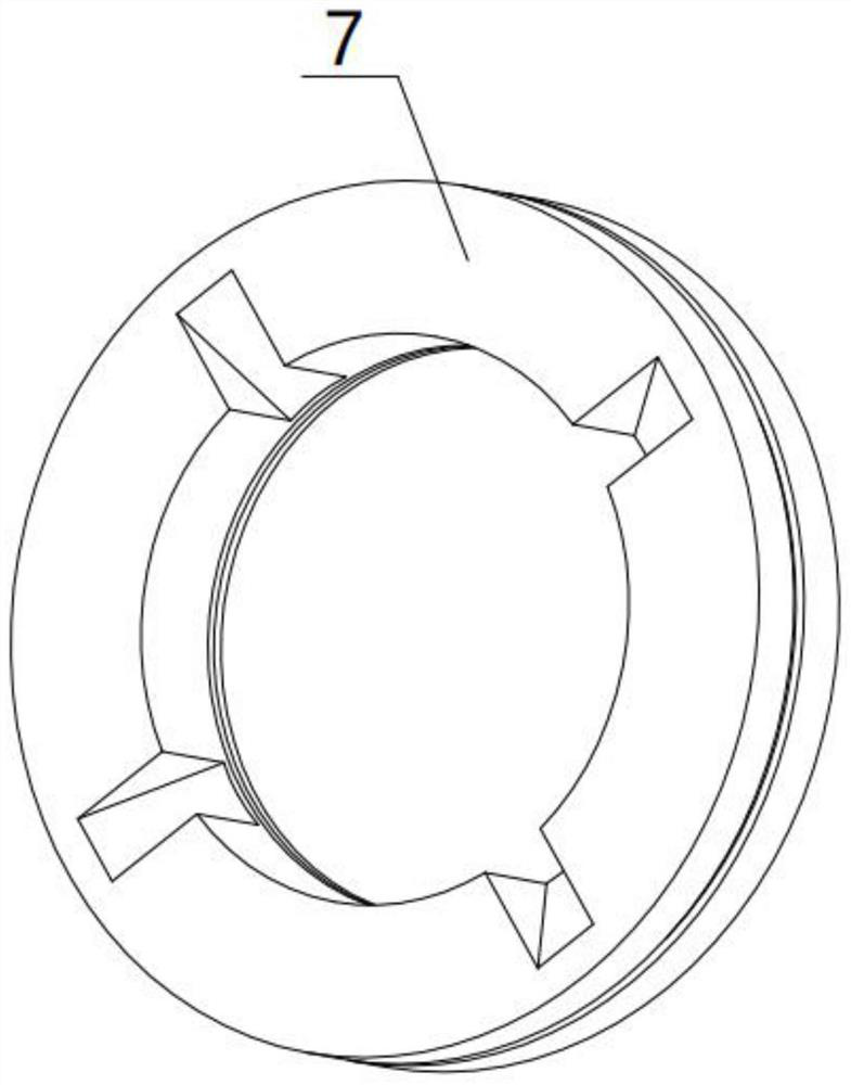
[0027] Refer figure 1 As shown, the present invention discloses a liquid static pressure bearing comprising: the main shaft 1, the shaft sleeve 2, the outer casing 3 and two sealing end caps 4; the inner wall of the shaft sleeve 2 has 4 oil cavities 5; the main shaft 1 Washed in the middle of the bushing 2; the bearing outer casing 3 is arranged outside of the shaft sleeve 2 and is fixedly joined together by the sealing end cap 4 and the shaft sleeve 2; the outer casing 3 and the bushing 2 form a working chamber. 6; the inside of the working chamber 6 is provided with a drive disk 7; one side of the driving disk 7 slidably disposed with four drive block 8, and the four drive block 8 is tilted along the drive plate 7; each driver block 8 passes One end of the reserved holes on the bushing 2 is provided with a modulation plate 9; the adjustment plate 9 is adapted to the oil chamber 5, and one or one is set.

[0028] A air hole 10 is provided on the bearing outer casing 3; the air ho...


PUM


Abstract

The invention discloses a hydrodynamic journal bearing which comprises a main shaft, a shaft sleeve, a bearing outer shell and two sealing end covers. A plurality of oil cavities are evenly distributed in the inner wall of the shaft sleeve, the main shaft is arranged in the middle of the shaft sleeve in a penetrating mode, the bearing outer shell is arranged on the outer side of the shaft sleeve in a sleeving mode, a working cavity is formed between the bearing outer shell and the shaft sleeve, a driving disc is arranged in the working cavity, a plurality of driving blocks are arranged on one side of the driving disc in a sliding mode, and an adjusting plate is arranged at the end, penetrating through a preformed hole in the shaft sleeve, of each driving block. According to the hydrodynamic journal bearing provided by the invention, the pressure of compressed air injected into air holes is adjusted. The driving disc can be controlled to reciprocate in the horizontal direction, so that all the driving blocks are driven to synchronously contract inwards or expand outwards in the direction perpendicular to the main shaft, the adjusting plate is driven to reciprocate, a gap between each oil cavity and the main shaft is changed, the thickness of an oil film is adjusted, the machining requirements of different products are met, the machining precision is improved, and the service life is prolonged.

Description

Technical field [0001] The present invention relates to the field of static pressure bearing, and more particularly to a liquid static pressure bearing. Background technique [0002] Liquid static pressure bearing is an outer supply pressure oil, establishing a static pressure carrying oil film inside the bearing to achieve a liquid lubricating sliding bearing, having high rotation precision, high rigidity, stable rotation, no vibration, etc., is widely used Ultra-precision machine. The change in the rotational speed of the liquid static pressure bearing will affect the thickness of the oil film and the pressure of the oil film, wherein the gap between the main shaft and the oil chamber is essential. Due to the different types of workpieces and processing requirements, the bearing can be changed in a large speed range, and to ensure the rotation accuracy and stability of the spindle, however, the current liquid static pressure bearing between the oil cavity When the gap is exit, ...

Claims


Application Information

Patent Timeline
Patent Type & Authority Applications(China)
IPC IPC(8): F16C32/06
CPCF16C32/067F16C32/0629
Inventor 陈万群滕翔宇霍德鸿陈高强丁辉
Owner JIANGSU JITRI JINGKAI HIGH VALUE MFG CO LTD
Learn More