
Cooling device for alloy material production

A technology of cooling device and alloy material, which is applied in the direction of furnace material, charging treatment type, lighting and heating equipment, etc., and can solve the problems of impurity precipitation, pipeline blockage, cooling effect decline, etc.

Pending Publication Date: 2021-12-24
江苏锡沂钢模有限公司
View PDF1 Cites 0 Cited by
  • Summary
  • Abstract
  • Description
  • Claims
  • Application Information

AI Technical Summary

Problems solved by technology

[0006] The object of the present invention is to provide a cooling device for the production of alloy materials, which solves the problems in the background art that the cooling effect will decrease due to the increase in temperature after a long time of work, and the cooling liquid will be damaged when working in a high temperature environment for a long time. Impurities precipitate, causing pipe blockage or adhesion to the inner wall of the water-cooling pipe, resulting in a decrease in cooling effect

Method used


Image

  • Cooling device for alloy material production
  • Cooling device for alloy material production
  • Cooling device for alloy material production

Examples


Embodiment 1

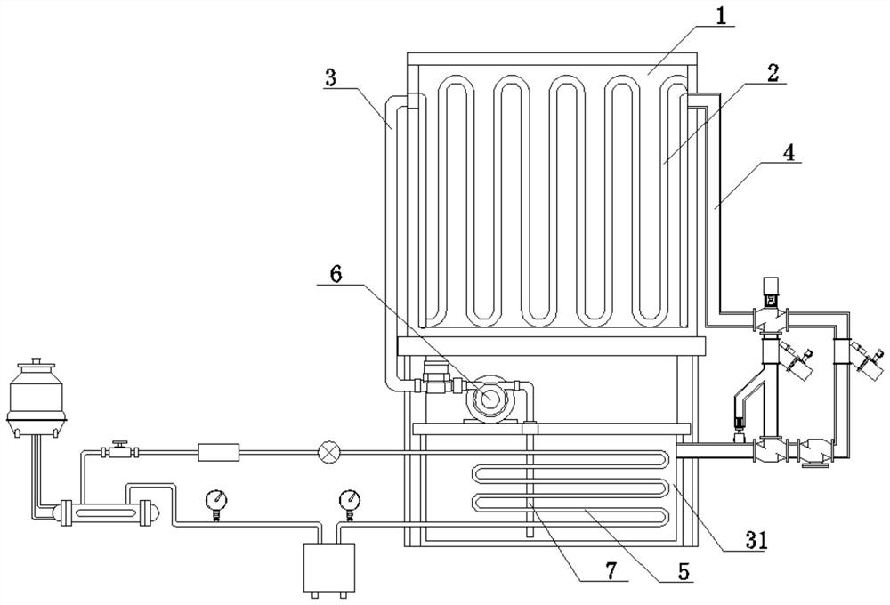
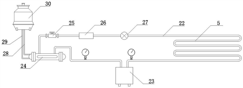
[0039] A cooling device for the production of alloy materials, comprising a furnace 1, the interior of the furnace 1 is provided with a water cooling wall 2, the water cooling wall 2 is connected with a water inlet pipe 3 and a water outlet pipe 4, one end of the water inlet pipe 3 is connected with a water cooling box 31, and the water outlet pipe One end of 4 is connected to the water-cooled box 31, the outlet pipe 4 is connected with a filter module, and the water-cooled box 31 is provided with an evaporating pipe 5 inside, and the evaporating pipe 5 is connected with a cooling module; The water inlet of the pump 6 is connected with a water suction pipe 7 , and the water suction pipe 7 is located inside the water cooling box 31 .

[0040] (see figure 1 )

[0041]The filter module includes a working filter tube 8 and a spare filter tube 9. One end of the working filter tube 8 is connected to the outlet pipe 4, the other end of the working filter tube 8 is connected to an el...

specific Embodiment approach

[0046] 1. A smelting barrel is set in the furnace 1, and the smelting barrel is located between the water walls 2;

[0047] Two, the melting furnace 1 starts the circulating pump 6 after the smelting is finished, and the circulating pump 6 extracts the coolant in the water-cooled tank 31 through the suction pipe 7, and imports it into the water-cooled wall 2 through the water inlet pipe 3 to cool the smelting barrel;

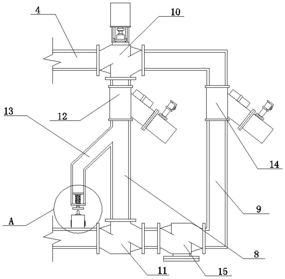
[0048] 3. After passing through the water wall 2, the coolant passes through the outlet pipe 4 and is introduced into the working filter pipe 8 by the electric three-way valve 10. The working filter 12 filters the coolant, and at the same time, part of the coolant enters the guide pipe 13, and the fluid of the coolant The pressure makes the piston plate 19 drive the compression spring 21 to press down, and the piston plate 19 drives the push plate 20 to descend through the slide rod 18 to trigger the travel switch 17, and the travel switch 17 controls the electri...


PUM


Abstract

The invention discloses a cooling device for alloy material production. A water cooling wall is arranged in a smelting furnace, the water cooling wall is connected with a water inlet pipe and a water outlet pipe, one end of the water inlet pipe is connected with a water cooling box, one end of the water outlet pipe is connected to the water cooling box, the water outlet pipe is connected with a filtering module, an evaporation pipe is arranged in the water cooling box, and the evaporation pipe is connected with a cooling module. According to the cooling device for alloy material production, the filtering module is arranged to filter impurities precipitated in cooling liquid, so that the impurities are prevented from blocking a pipeline or adhering to the inner wall of the water cooling pipe to reduce the cooling effect; meanwhile, by arranging a standby filter pipe, the cooling liquid can flow through the standby filter pipe when a working filter is blocked, the cooling liquid is filtered through a standby filter, and it can be guaranteed that the cooling device continues to operate when a worker replaces a filter element of the working filter; a cooling assembly is arranged in the water cooling box, the cooling liquid in the water cooling box can be cooled through the evaporation pipe, and the problem that the cooling effect is reduced due to the fact that the temperature of the cooling liquid rises after long-time work is avoided.

Description

technical field [0001] The invention relates to the technical field of alloy production, in particular to a cooling device for alloy material production. Background technique [0002] A metal material with metallic properties that is usually formed by adding two or more metal elements or other non-metallic elements based on metals through an alloying process (smelting, mechanical alloying, sintering, vapor deposition, etc.) is called an alloy. . [0003] Melting is a technique for producing alloys by melting metallic materials such as aluminum and iron together at high temperatures. Alloys are generally made by smelting in a smelting furnace. During the smelting process, it was found that after the smelting of the low-carbon ferrochrome alloy was completed, the temperature of the smelting furnace was too high to cool quickly, and it could only be cooled by natural cooling. Hidden dangers, at the same time, the staff need to wait a lot of time to clean the melting furnace, ...

Claims


Application Information

Patent Timeline
Patent Type & Authority Applications(China)
IPC IPC(8): F27B14/08B01D35/02B01D35/12
CPCF27B14/08B01D35/02B01D35/12F27B2014/0837F27M2003/13
Inventor 李堃刘磊李贺黄伟殷家乐姜民
Owner 江苏锡沂钢模有限公司
Learn More