
Fault diagnosis method for core unit of flexible printing electronic equipment

A technology for fault diagnosis and electronic equipment, applied in neural learning methods, measuring devices, computer security devices, etc., can solve problems such as cracks, limiting the improvement of stability and precision of flexible printed electronic equipment, product failure, etc., to achieve complex processes, The effect of improving long-term operation benefits and reducing operation and maintenance costs

Pending Publication Date: 2021-12-24
XIAN UNIV OF TECH
View PDF4 Cites 0 Cited by
  • Summary
  • Abstract
  • Description
  • Claims
  • Application Information

AI Technical Summary

Problems solved by technology

The printing accuracy of roll-to-roll flexible printed electronic equipment reaches the precision requirement of 10 microns. Any slight abnormal vibration of the equipment will affect the stability of its operation and even cause failures.
Roll-to-roll failures include two types of component failures (such as wear of gears, bearings, and couplings) and adjustment failures (due to improper installation or adjustment, resulting in non-parallel roll-to-roll rollers, local friction, etc.), which will make the base The deviation, wrinkling, uneven tension, and inaccurate overprinting of the material will cause fracture, crack, and peeling of the multi-layer heterogeneous structure of the flexible electronic device, resulting in product failure, decreased precision, and quality fluctuations, which seriously limit the The stability and accuracy of flexible printed electronic equipment are improved, so it is of great application value to carry out research on roll-to-roll fault diagnosis

Method used


Image

  • Fault diagnosis method for core unit of flexible printing electronic equipment
  • Fault diagnosis method for core unit of flexible printing electronic equipment
  • Fault diagnosis method for core unit of flexible printing electronic equipment

Examples


Embodiment Construction

[0051] In order to make the object, technical solution and advantages of the present invention clearer, the present invention will be further described in detail below in conjunction with the accompanying drawings.

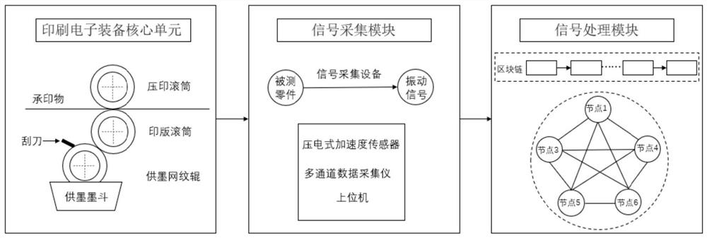
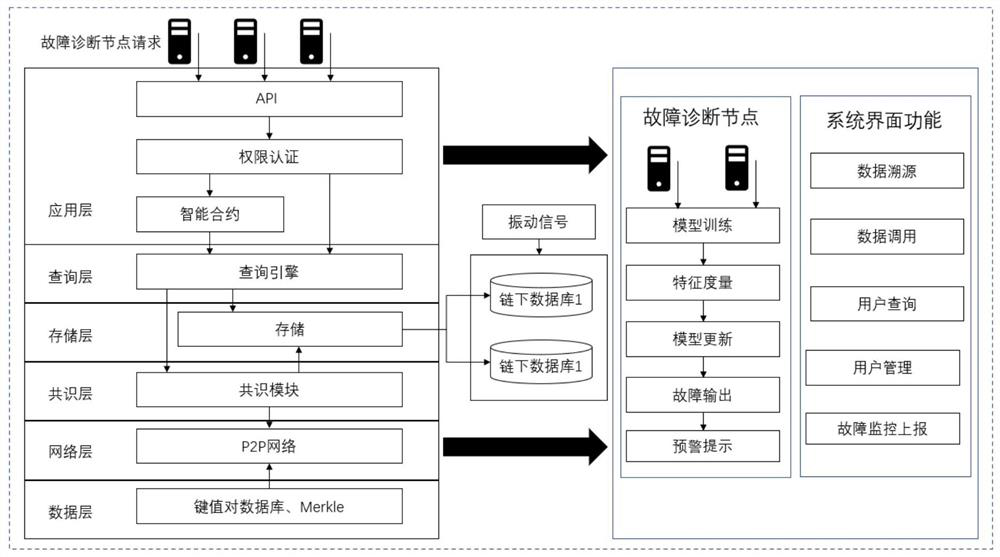
[0052] The following illustrates the exemplary application of the block chain network provided by the present invention, see figure 2 , figure 2 It is a schematic diagram of the fault diagnosis module of the core unit of printed electronic equipment based on blockchain technology provided by the present invention, including a core unit module of printed electronic equipment, a signal acquisition module and a signal processing module.

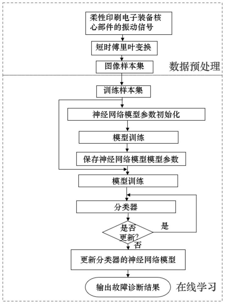
[0053] The specific operation method of a flexible printed electronic equipment core unit fault diagnosis method of the present invention is as follows: figure 1 Shown:

[0054] (1) Printed electronic equipment core unit module

[0055] Step 1: If figure 2 As shown in the core unit module of flexible printed electronic equipm...


PUM


Abstract

The invention discloses a fault diagnosis method for a core unit of flexible printing electronic equipment, and aims to realize an interactive system which can acquire vibration signals of core parts of the flexible printing electronic equipment in real time, and then quickly diagnose and feed back the vibration signals. The system has the advantages of being high in response speed, large in data storage amount, low in cost, high in safety and reliability, high in data traceability and confidentiality and the like. The method comprises the following steps: continuously collecting vibration signals in a running state of a core component of the flexible printing electronic equipment, packaging and chaining the vibration signals, continuously diagnosing the vibration signals, sharing a fault diagnosis algorithm, dynamically storing data, responding in real time and quickly diagnosing. According to the method, the blockchain can be utilized to realize dynamic storage of the data, improve the calling efficiency of the data and improve the diagnosis speed, and the fault diagnosis algorithm can be continuously updated to realize continuous optimization of the algorithm and simultaneous diagnosis of multiple algorithms.

Description

technical field [0001] The invention adopts blockchain technology and relates to a fault diagnosis method for a core unit of flexible printed electronic equipment. Background technique [0002] With the continuous development and transformation of industrial intelligence, the market demand for new components such as new sensors and flexible electronics is gradually expanding. In this context, the flexible printed electronics industry has become one of the key industries in the industrial informatization revolution. The development of flexible printed electronics technology not only eliminates the deposition, photolithography, etching and other processes in the manufacture of traditional electronic components, but also breaks through Limitations of placing electronic components on flat panels. Roll-to-roll flexible printed electronics has become the main means of industrial production of flexible printed electronics because it overcomes the disadvantages of inkjet flexible p...

Claims


Application Information

Patent Timeline
Patent Type & Authority Applications(China)
IPC IPC(8): G06K9/62G06N3/04G06N3/08G06K9/00G06F21/64G06F21/62G06F21/60G01H17/00
CPCG06N3/04G06N3/084G06F21/64G06F21/602G06F21/6218G01H17/00G06F2218/02G06F18/2414
Inventor 徐卓飞武丽花刘善慧赵庆海李恒刘显萌
Owner XIAN UNIV OF TECH
Learn More