Four-mode dielectric waveguide filter

A dielectric waveguide and filter technology, applied in the field of four-mode dielectric waveguide filter, can solve the problems of waste mode, no polarization degeneracy, large thickness of dielectric block, etc., and achieve the effect of reducing the number of cavities

Active Publication Date: 2021-12-24
SOUTH CHINA UNIV OF TECH
View PDF8 Cites 0 Cited by
  • Summary
  • Abstract
  • Description
  • Claims
  • Application Information

AI Technical Summary

Problems solved by technology

[0003] The existing multi-mode technology mainly has the following disadvantages: First, some multi-mode filters only use the most basic three modes of the waveguide cavity, and couple through corner cutting. The size of this filter is relatively fixed, and the thickness of the dielectric block Too large, not conducive to the reduction of base station height
Second, some multimode dielectric waveguide filters use high-order modes, which will generate parasitic passbands in the low frequency band
Although some do not use high-order modules, they do not use extreme reduction, wasting a model
Third, the volume of some multi-mode cavities is equivalent to the volume of multiple single-mode cavities cascaded, which does not play a role in miniaturization

Method used


Image

  • Four-mode dielectric waveguide filter
  • Four-mode dielectric waveguide filter
  • Four-mode dielectric waveguide filter

Examples


Embodiment 1

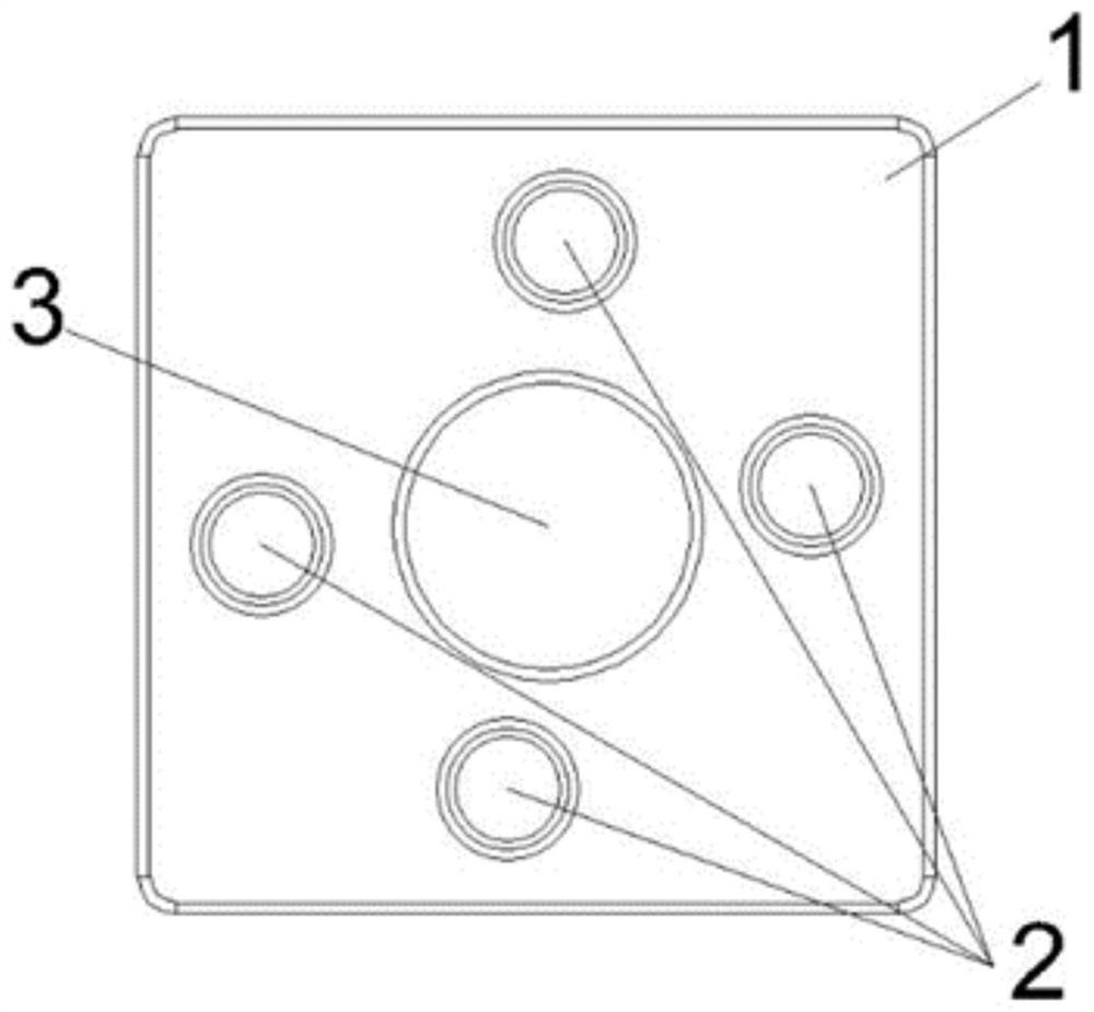
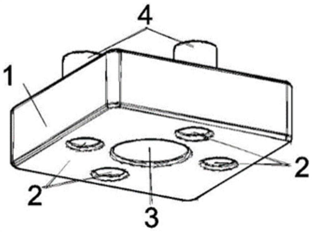
[0022] see figure 1 and figure 2 As shown, this embodiment provides a single-cavity four-mode dielectric waveguide filter, including a silver-plated ceramic dielectric body 1 (in a rectangular shape), the bottom of the dielectric body 1 is connected to a coaxial connector 4, and the coaxial connection The filter 4 is used as the input and output ports to feed the filter, and the embedded depth of the coaxial inner conductor determines the external quality factor of the input and output ports, and determines the electromagnetic field energy entering the filter. The entire dielectric body 1 is formed with only one resonant cavity, and a four-mode structure is set on the top of the resonant cavity. The four-mode structure includes four tuning blind holes 2 and a coupling through hole 3 for adjusting coupling, and two tuning blind holes 2 are located in the Near the transverse centerline of the cavity, the other two tuning blind holes 2 are located near the longitudinal centerli...

Embodiment 2

[0027] Different from Embodiment 1, what this embodiment provides is a multi-cavity four-mode dielectric waveguide filter (not shown in the figure), and coupling through holes are arranged between adjacent resonant cavities of the filter to introduce magnetic coupling, Electric coupling is introduced by setting coupling blind holes; among them, the resonant cavity without four-mode structure can be equipped with a single tuning blind hole at the top or bottom of the cavity to adjust the frequency of the single mode, or without tuning blind holes, by changing The length, width and height of the cavity are used to change the resonant frequency.


PUM


Abstract

A four-mode dielectric waveguide filter disclosed by the present invention comprises a dielectric body with a conductive coating on the surface, the dielectric body can be divided into a plurality of resonant cavities, the top of at least one resonant cavity is provided with a four-mode structure, and the four-mode structure comprises four tuning blind holes and a coupling through hole, wherein two tuning blind holes are distributed near the transverse center line of the resonant cavity body, the other two tuning blind holes are distributed near the longitudinal center line of the resonant cavity body, and a coupling through hole is formed in the middle position of the resonant cavity body or close to the center of the resonant cavity body. The four-mode structure enables a TE101 mode, a TE201 mode, a TE102 mode and a TE202 mode to become four modes with the lowest frequency in the cavity, so that the four-mode filter is realized. Four modes are applied in one resonant cavity, the number of resonant cavities needed by the filter can be reduced, the size of the filter is further reduced, and the device miniaturization is achieved.

Description

technical field [0001] The invention relates to the technical field of radio frequency and microwave filters, in particular to a four-mode dielectric waveguide filter. Background technique [0002] In recent years, my country's 5G communication base station construction has been steadily advancing, and 5G base station filters have become a research hotspot. my country's 5G mainstream frequency band has 64 channels, and the required filters are 8 to 16 times that of 4G. Moreover, the filter has been integrated into the active unit of the antenna with a large-scale multiple-input multiple-output antenna, which puts forward higher requirements on the volume of the filter. Therefore, using multimode technology to miniaturize dielectric waveguide filters has extremely high application value. [0003] The existing multi-mode technology mainly has the following disadvantages: First, some multi-mode filters only use the most basic three modes of the waveguide cavity, and couple th...

Claims


Application Information

Patent Timeline
IPC IPC(8): H01P1/20H01P1/208
CPCH01P1/2002H01P1/2086
Inventor 褚庆昕麦健业
Owner SOUTH CHINA UNIV OF TECH
Why Eureka
Try Eureka