
Nitrogen-oxygen sensor ceramic chip core

A nitrogen and oxygen sensor and ceramic sheet technology, applied in the field of nitrogen and oxygen sensors, can solve problems such as sensor failure

Active Publication Date: 2020-07-31
江苏惟哲新材料有限公司
View PDF11 Cites 0 Cited by
  • Summary
  • Abstract
  • Description
  • Claims
  • Application Information

AI Technical Summary

Problems solved by technology

[0005] Aiming at the problem that there are many cavities in the traditional ceramic core and the setting of the reference airway may cause the sensor to fail, the present invention provides a nitrogen and oxygen sensor ceramic core, which reduces the cavity structure and thus simplifies the processing technology and reduces the The possibility of product defects due to the need to process too many cavities, while also omitting the reference airway, will not cause sensor failure due to reference airway contamination

Method used


Image

  • Nitrogen-oxygen sensor ceramic chip core
  • Nitrogen-oxygen sensor ceramic chip core
  • Nitrogen-oxygen sensor ceramic chip core

Examples


Embodiment Construction

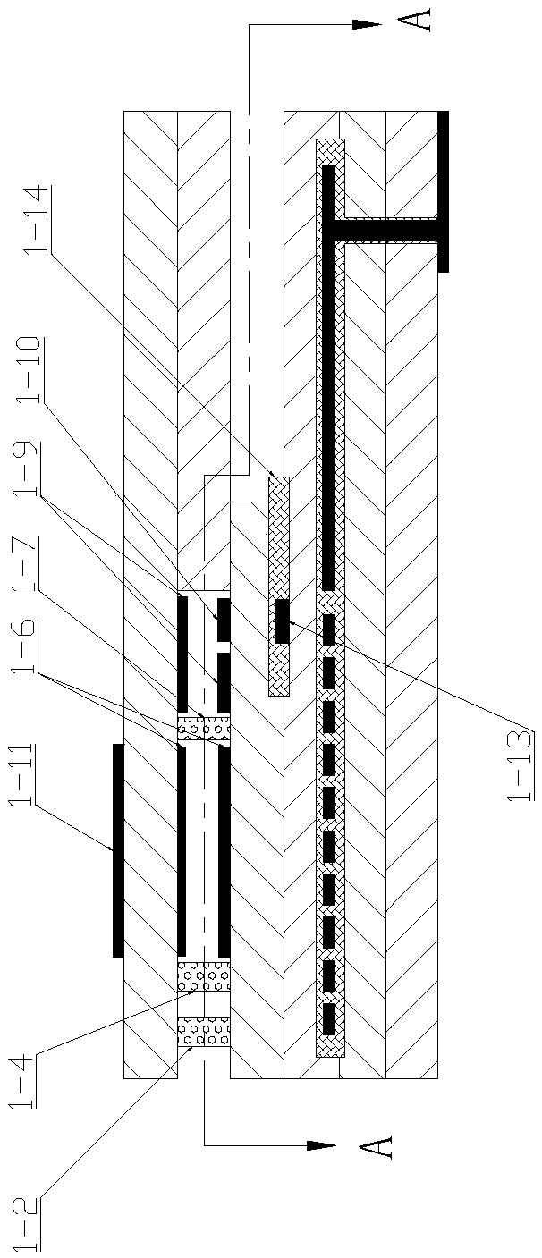
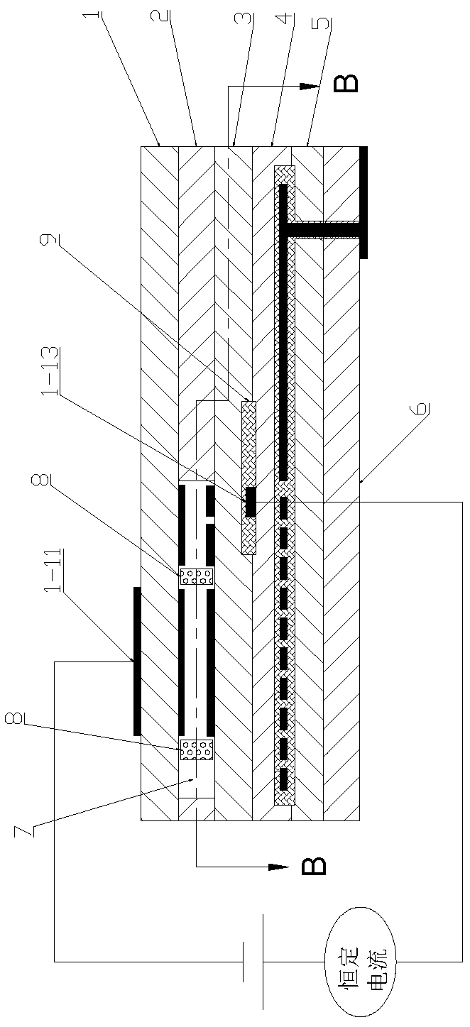
[0016] like image 3 , Figure 4 A nitrogen-oxygen sensor ceramic chip is shown, which includes a first substrate 1, a second substrate 2, a third substrate 3, a fourth substrate 4, a fifth substrate 5 and a sixth substrate arranged up and down. Sheet 6, external electrodes 1-11 are mounted on the outside of the first substrate 1, reference electrodes 1-13 are mounted between the third substrate 3 and the fourth substrate 4, and the middle of the second substrate 2 is sequentially provided with exhaust gas treatment The chamber 7, the first detection chamber 1-5 and the second detection chamber 1-8, the exhaust gas treatment chamber 7, the first detection chamber 1-7 and the second detection chamber 1-8 are provided with a gas diffusion barrier 8, and the exhaust gas treatment There are gas diffusion barriers 8 at the fronts of both sides of the cavity 7 and the front ends are closed; only a mounting cavity 9 for mounting the reference electrodes 1-13 is opened between the th...


PUM


Abstract

The invention provides a nitrogen-oxygen sensor ceramic chip core which has the advantages that the cavity structure is reduced so that the processing technology is simplified, the possibility of product defects caused by processing excessive cavities is reduced and a reference air passage is omitted and the problem of sensor failure caused by reference air passage pollution is avoided. The nitrogen-oxygen sensor ceramic chip core comprises first to sixth substrates which are arranged vertically. An outer electrode is installed on the outer side of the first substrate, a reference electrode isinstalled between the third substrate and the fourth substrate, a tail gas treatment cavity, a first detection cavity and a second detection cavity are sequentially formed in the middle of the secondsubstrate, diffusion barriers are arranged among the tail gas treatment cavity, the first detection cavity and the second detection cavity, and diffusion barriers are arranged on the front portions of the two sides of the tail gas treatment cavity. Only a mounting cavity for mounting the reference electrode is formed between the third substrate and the fourth substrate, and oxygen in the tail gasis pumped into the mounting cavity by applying current between the outer electrode and the reference electrode so that the oxygen partial pressure in the mounting cavity is consistent with the oxygenpartial pressure in the atmosphere.

Description

technical field [0001] The invention relates to the technical field of nitrogen and oxygen sensors, in particular to a nitrogen and oxygen sensor ceramic chip. Background technique [0002] Nitrogen and oxygen sensor is a gas sensor used to detect nitrogen oxides in diesel vehicle exhaust. With the country's increasing emphasis on environmental protection, the emission regulations issued by the x The control of emission limits is also becoming stricter. To reduce NO in diesel vehicles x Emissions, a new selective catalytic reduction system (SCR) has been added to the engine exhaust system. The principle is that when the exhaust gas of the engine is discharged, urea is injected and mixed with it, and NH is used on the surface of the catalyst of the SCR system. 3 NO reduction x , reacts to the harmless N 2 . It is in this system that the nitrogen and oxygen sensor plays a role in monitoring NO x content to control the effect of urea injection amount. [0003] The chip...

Claims


Application Information

Patent Timeline
Patent Type & Authority Applications(China)
IPC IPC(8): G01N27/416
CPCG01N27/4162
Inventor 王纯强陈志赵锋
Owner 江苏惟哲新材料有限公司
Learn More