Automatic reciprocating type belt folding machine

A technology of reciprocating belt stacking machine, applied in the field of automatic reciprocating belt stacking machine, can solve the problems such as the deviation of the position of the steel wire rope belt and easy to collapse, so as to improve the work efficiency, prevent bending and breaking under pressure, and waste time. The effect of shortening time

Inactive Publication Date: 2021-12-28
安徽格锐鑫智能装备有限公司
View PDF0 Cites 0 Cited by
  • Summary
  • Abstract
  • Description
  • Claims
  • Application Information

AI Technical Summary

Problems solved by technology

[0005] The wire rope belt placed on the flatbed truck during the folding process is not equipped with anti-deviation equipment, which makes the wire rope belt prone to position deviation, and the steel wire belt belt with a higher height after stacking is prone to collapse under the vibration generated during the movement of the flatbed truck Case

Method used


Image

  • Automatic reciprocating type belt folding machine
  • Automatic reciprocating type belt folding machine
  • Automatic reciprocating type belt folding machine

Examples


Embodiment 1

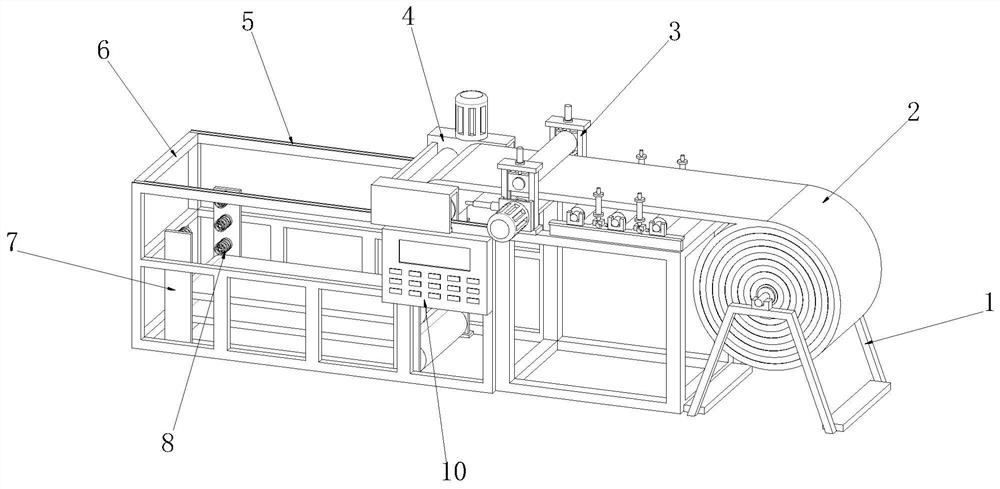
[0038] see Figure 1-4As shown, the automatic reciprocating belt stacking machine includes a discharge rack 1, a belt body 2, a drive frame 3, a swing frame 4, a walking track 5, a support frame 6 and an automatic control box 10, and one side of the upper surface of the support frame 6 is connected with The walking track 5, the side of the upper surface of the support frame 6 close to the walking track 5 is slidably connected with the swing frame 4, the side of the upper surface of the support frame 6 close to the swing frame 4 is connected with the drive frame 3, and the middle position inside the drive frame 3 is slidably connected There is a belt body 2, a discharge rack 1 is provided on one side of the outer wall of the support frame 6, an automatic control box 10 is connected to the front surface of the support frame 6 near the position of the drive frame 3, and a mounting plate 7 is connected to the front and rear sides of the inner wall of the support frame 6 ;

[0039...

Embodiment 2

[0043] The weight of the steel wire rope belt body 2 for mine is relatively heavy, and the weight of each roll of the belt body 2 is more than ten tons. After folding, the folded position has a higher protrusion, and the lower fold is under the gravity of the belt body 2 stacked above. Large deformation occurs, and the force received at the folded position of the bottom belt body 2 is relatively large, and it is easy to bend and break;

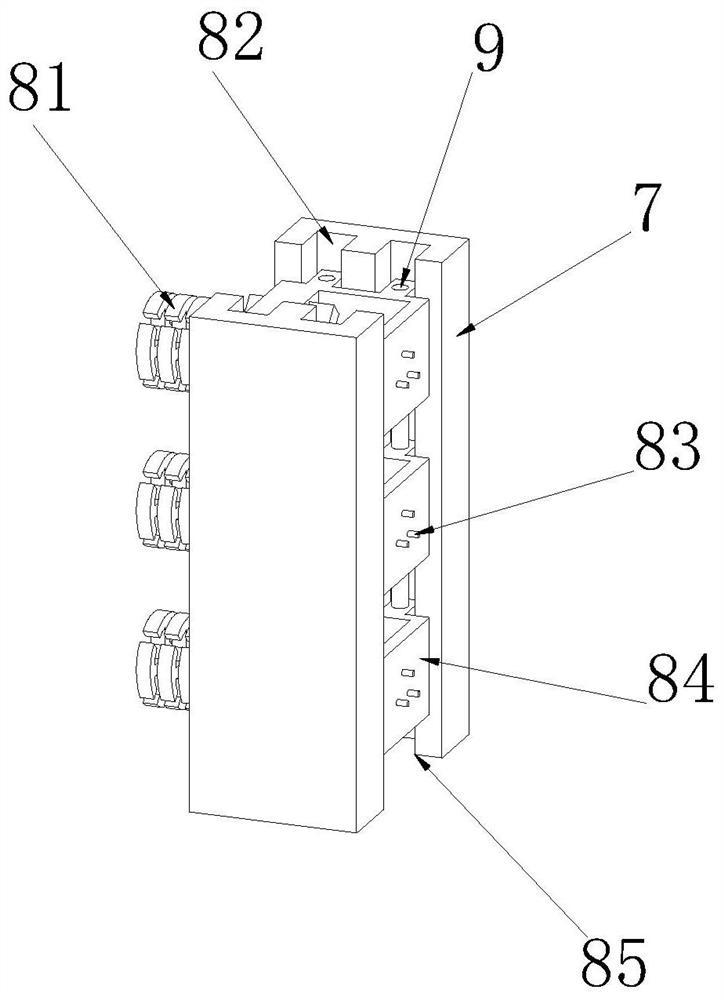
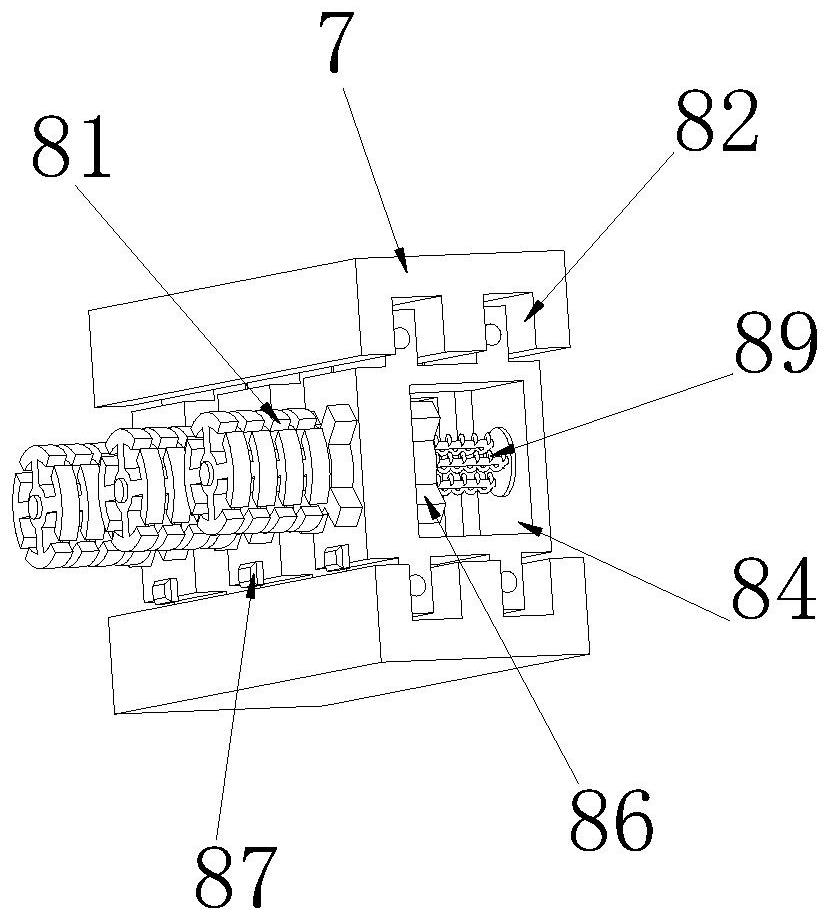
[0044] see Figure 4-6 As shown, the upper surface of the sliding frame 84 is provided with an elastic mechanism 9, the elastic mechanism 9 includes an elastic box 97, and the four directions inside the elastic box 97 are provided with movable chambers, and the outer wall of the elastic box 97 is provided with an adjustment hole corresponding to the position of the movable chamber. 96. The width of the adjustment hole 96 is smaller than the width of the inner space of the movable cavity. The inside of the adjustment hole 96 is slidably connect...

Embodiment 3

[0047] During the reciprocating folding process of the belt body 2, there is no shielding device at the middle position of the stacked belt body 2, which makes the position of the middle position of the belt body 2 prone to shift, and makes the belt body 2 with a higher height after stacking complete. It is prone to collapse due to skew;

[0048] see Figure 7-8 As shown, a limit mechanism 11 is arranged on both sides of the outer wall of the mounting plate 7, and the limit mechanism 11 includes a baffle plate 112, and a through hole 113 is provided on the front surface of the baffle plate 112 corresponding to the position of the auxiliary frame 81, and the size of the through hole 113 is the same as that of the auxiliary frame. The size of the circular structure formed by 81 is the same, so that the auxiliary frame 81 can slide freely in the inside of the through hole 113. There is a chute 114 at the position corresponding to the limit frame 111 on the side, and the limit fr...


PUM


Abstract

The invention relates to a steel wire rope belt folding technology, and particularly relates to an automatic reciprocating type belt folding machine which is used for solving the problems that in the reciprocating folding process of a steel wire rope belt, the work efficiency is affected due to long moving distance, and collapse is caused by bending breakage and position deviation at the folding position due to the pressure effect. The automatic reciprocating type belt folding machine comprises a discharging frame, a belt body, a driving frame, a supporting frame and an automatic control box, a walking rail is connected to one side of the upper surface of the supporting frame, and a swing frame is slidably connected to one side, close to the walking rail, of the upper surface of the supporting frame. According to the automatic reciprocating type belt folding machine, the moving distance of the swing frame is shortened by limiting the position movement of the steel wire rope belt through an auxiliary frame, the work efficiency of the belt folding machine is improved, the folding position of the steel wire rope belt is supported by the auxiliary frame under the supporting of an elastic cushion, the folding position of the steel wire rope belt is prevented from being bent and broken, and the steel wire rope belt is blocked by a baffle so that the collapse caused by position deviation is prevented.

Description

technical field [0001] The invention relates to a wire rope belt folding technology, in particular to an automatic reciprocating belt folding machine. Background technique [0002] When replacing the steel wire rope belts used in coal mines, it is necessary to stack the coiled belts on the flatbed on the ground for transportation and downhole. Each roll of belt weighs more than ten tons. Manual belt stacking not only consumes a lot of manpower, but also has low stacking efficiency and poses a great safety hazard. [0003] When the belt stacking machine folds the wire rope belt reciprocally, the swing frame turns and pulls the wire rope belt to move in the opposite direction to fold the wire rope belt. The wire rope belt is bent at the folding position and has a long length. Therefore, when the swing frame is folded, it needs to pass through the folding position, continue to move for a certain distance, and then move in the reverse direction, so that the reciprocating distan...

Claims


Application Information

Patent Timeline
Patent Type & Authority Applications(China)
IPC IPC(8): B65H45/107
CPCB65H45/107B65H2701/19
Inventor 王岩劳凤喜武波洪东炳黄志祥任安才詹同伟石磊
Owner 安徽格锐鑫智能装备有限公司
Why Eureka
Try Eureka