
Concrete continuous tooth wall structure without structural joints and construction method

A technology for concrete and structural joints, applied in infrastructure engineering, construction, etc., can solve problems such as affecting the economic benefits of power stations or reservoirs, difficult to accurately find the location of defects, difficult to connect or seal, etc., to avoid a large number of leakage or venting repairs The work and construction are less difficult, and the effect of reducing the heat of cement hydration

Pending Publication Date: 2021-12-28
POWERCHINA HUADONG ENG COPORATION LTD +1
View PDF3 Cites 0 Cited by
  • Summary
  • Abstract
  • Description
  • Claims
  • Application Information

AI Technical Summary

Problems solved by technology

[0004] 1. The tooth wall is provided with structural joints every 10-20m, and the construction is troublesome
[0005] 2. The water stop is installed at the structural joints, which becomes the weak link of anti-seepage. During the construction, there are often vibrations and incomplete compaction near the water stop, and the construction quality is difficult to control
[0006] 3. Due to the large number of structural joints, if the leakage of the dam and reservoir basin is large after the water storage operation, it is difficult to accurately find the location of the defect, and the reinforcement is difficult and time-consuming, which affects the economic benefits of the power station or reservoir
[0007] 4. It is difficult to connect or seal the water stop in the structural joint and the surface anti-seepage body (such as geomembrane, asphalt concrete panel, etc.)

Method used


Image

  • Concrete continuous tooth wall structure without structural joints and construction method
  • Concrete continuous tooth wall structure without structural joints and construction method
  • Concrete continuous tooth wall structure without structural joints and construction method

Examples


Embodiment Construction

[0038] In order to enable those skilled in the art to better understand the technical solutions of the present invention, the preferred embodiments of the present invention will be described below in conjunction with specific examples, but it should be understood that the accompanying drawings are for illustrative purposes only, and cannot be interpreted as an explanation of this patent. Restrictions; In order to better illustrate this embodiment, some parts in the drawings will be omitted, enlarged or reduced, and do not represent the size of the actual product; for those skilled in the art, some known structures and their descriptions in the drawings may Omissions are understandable. The positional relationship described in the drawings is for illustrative purposes only, and should not be construed as a limitation on this patent.

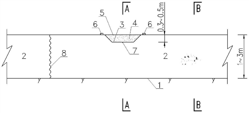
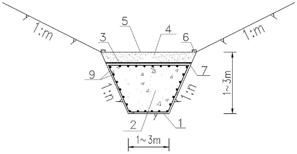
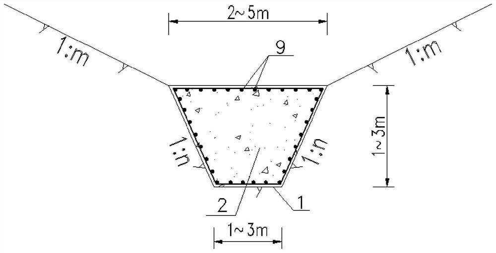
[0039] Attached below Figure 1~3 and Examples further illustrate the present invention, but not as a basis for limiting the present invention. ...


PUM


Abstract

The invention discloses a concrete continuous tooth wall structure without structural joints. The concrete continuous tooth wall structure comprises a concrete tooth wall which is arranged in a full-length mode and is not provided with the structural joints, a plurality of grooves are formed in the top of the concrete tooth wall at intervals, induction joints are formed in the bottoms of the grooves, silty-fine sand soil is laid in the grooves, and geotechnical cloth covers the silty-fine sand soil. The concrete continuous tooth wall structure is suitable for hydropower and hydraulic engineering adopting concrete tooth wall seepage prevention, through structural arrangement type optimization design, structural parting is canceled, the construction procedure is simplified, long-term operation safety of dam and reservoir seepage prevention systems is guaranteed, and economic losses caused by maintenance after reservoir water storage are reduced.

Description

technical field [0001] The invention relates to the field of hydropower and hydraulic engineering, in particular to a concrete continuous tooth wall structure without structural joints. Especially when it comes to dam cutoff walls, there are local surface anti-seepage requirements, and the reservoir basin project needs to set up seepage interception around the concrete tooth wall. Background technique [0002] For dam cut-off walls or reservoirs that require partial surface anti-seepage, concrete tooth walls are generally installed on the edge of the dam foundation and anti-seepage area, and curtain grouting is arranged to cut off the gap between the reservoir water and the bottom of the anti-seepage area. Hydraulic connection. Due to the long dams and large reservoir basins of some projects, some concrete tooth walls are hundreds of meters long. In order to prevent cracks in the tooth wall, structural joints are generally set every 10-20m to adapt to its deformation. [...

Claims


Application Information

Patent Timeline
IPC IPC(8): E02D19/18
CPCE02D19/18
Inventor 王樱畯汪剑国赵琳姚敏杰李高会
Owner POWERCHINA HUADONG ENG COPORATION LTD
Learn More