Mining medium-length hole drilling and blasting method

A technology of deep holes and blastholes, which is applied in the field of deep hole rock drilling and blasting in mining, can solve the problems of high cost of rock drilling and blasting, and difficulty in adjusting the charge amount, so as to reduce the cost of rock drilling and blasting, reduce mining costs, Reduced the effect of blast shock waves and seismic waves

Pending Publication Date: 2021-12-28
海南矿业股份有限公司
View PDF0 Cites 2 Cited by
  • Summary
  • Abstract
  • Description
  • Claims
  • Application Information

AI Technical Summary

Problems solved by technology

Since the same row of blastholes has the same diameter, it is difficult to adjust the charge amount when the charge length of each blasthole is constant, resulting in higher costs for rock drilling and blasting in the mining process.

Method used


Image

  • Mining medium-length hole drilling and blasting method

Examples


Embodiment 1

[0016] The northern ore body of Meishan Iron Mine is a branch of the main ore body. The ore body elevation is -89m. The mining method of ramp development and sub-column caving is adopted. The test block stope structure parameters at the end of the ore body are 16m×15m, the route section is 4.5m×3.8m, there are two kinds of parameters for mining medium and deep hole rock drilling blasting, among them: the blast hole diameter of the N6# and N7# recovery routes is φ78mm, the row spacing is 2.2m, the hole bottom The hole distance is 2.0~2.2m, the side hole angle is 55°, the blast hole diameter of N8# and N9# recovery approach is φ72mm, the row spacing is 2.0m, the hole bottom distance is 2.2~2.6m, and the side hole angle is 55°. The CTC-141 pneumatic rock drilling jumbo is equipped with the YG90 rock drill for mining medium and deep hole operations, and the BQF-100 chargeer is used for mining medium and deep hole charge operations.

[0017] According to the present invention, when...

Embodiment 2

[0019] Shilu Iron Mine is a large-scale open-pit-to-underground mine. It adopts the joint development of shafts and slopes, and the mining method of segmental caving without pillars. The stope structure parameters are 15m×18m, and the approach section is 4.5m×3.8m.- The parameters of deep hole rock drilling in 60m segmental mining are: blasthole diameter φ87mm, row spacing 2.2m, hole bottom distance 3.2~3.4m, side hole angle 50°, center of rotation (double center) height 1.85m , each row of 8 gun holes. The SimbaH1354 full-hydraulic rock drilling rig is used with the cop1838 rock drill for mining medium and deep hole operations, and the BQF-100 chargeer is used for mining medium and deep hole charge operations.

[0020] According to the invention, in the design of deep holes in mining, according to the requirements of the explosiveness of ore rock and the step distance of ore collapse, the blast hole diameters are φ87mm and φ78mm, and the blast hole row spacing=25~40×Blast hol...


PUM


Abstract

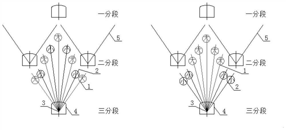
The invention discloses a mining medium-length hole drilling and blasting method, and relates to the technical field of underground mining. The mining medium-length hole drilling and blasting method comprises the steps that medium-length holes in mining are constructed by pneumatic or hydraulic drilling equipment in a subsection plane stoping route and then are charged and blasted, the whole medium-length holes in mining are arranged in a fan-shaped or parallel mode, and more than two different diameters are arranged in a staggered or bunchy mode; and charging blasting is carried out according to different arrangement forms, large-diameter blast holes are firstly detonated, and small-diameter blast holes are then detonated. The small-diameter blast holes are high in rock drilling efficiency, small in explosive loading amount and less in harmful gas generated by blasting, the rock drilling and blasting cost can be reduced under the condition that the blasting effect is not affected, so that the mining efficiency is improved, and the mining cost is reduced; and the blast holes with different diameters are detonated by different sections of detonators, the large-diameter blast holes play a main blasting role and are detonated firstly, and the small-diameter blast holes play an auxiliary blasting role and then are detonated, so that blasting shock waves and seismic waves are reduced.

Description

technical field [0001] The invention relates to the technical field of underground mining, in particular to a method for deep hole rock drilling and blasting in mining. Background technique [0002] The underground mining methods of metal deposits are mainly divided into three categories: open-field mining method, caving mining method, and filling mining method. Each major mining method can be divided into many sub-categories. Rock drilling and blasting is the main method for mining ore in mines, and large-scale mines all use medium and deep hole rock drilling and blasting. [0003] Take the segmental caving method without pillars as an example for illustration. [0004] Pillarless segmental caving method is a mining method with simple structure, convenient management, safety and high efficiency. It has been widely used in underground mines at home and abroad. At present, this mining method is developing in the direction of large structural parameters and large mining equip...

Claims


Application Information

Patent Timeline
Patent Type & Authority Applications(China)
IPC IPC(8): E21C41/22F42D3/04
CPCE21C41/22F42D3/04
Inventor 范庆霞何青松
Owner 海南矿业股份有限公司
Why Eureka
Try Eureka