Ship navigation signal lamp inspection method based on unmanned aerial vehicle

An inspection method and signal light technology, which are applied in the field of UAV-based ship navigation signal light inspection, can solve the problems that the inspection results cannot be qualified at one time, the ship trial period is unfavorable, and the coordinate points cannot be confirmed, so as to shorten the trial period and save labor. Cost and tugboat fuel consumption, etc., and the effect of improving inspection safety

Pending Publication Date: 2021-12-28
COSCO ZHOUSHAN SHIPYARD
View PDF0 Cites 0 Cited by
  • Summary
  • Abstract
  • Description
  • Claims
  • Application Information

AI Technical Summary

Problems solved by technology

[0003] 1. After the ship is launched, the general cycle is relatively long, which is not conducive to the inspection of navigation signal lights by drones, and the coordinate points cannot be confirmed;
[0004] 2. Using the traditional method to inspect navigation signal lights requires the cooperation of tugboats to inspect one by one at sea, running around the ship, front, back, left, and right, and the wind and waves are strong. The inspection results are often not qualified at one time, which is time-consuming and laborious;
[0005] 3. When using tugboats to cooperate with the inspection of navigation lights, there are many people participating in the inspection, and the safety risk is greater, which is not good for the ship trial period
[0006] In summary, the existing navigation signal light inspection methods have the disadvantages of low efficiency, poor safety, and high cost. It is necessary to develop an inspection method with high efficiency, simple operation, low cost and high safety to meet the inspection needs of navigation signal lights.

Method used


Image

  • Ship navigation signal lamp inspection method based on unmanned aerial vehicle

Examples


Embodiment Construction

[0022] The present invention will be further described in detail below in conjunction with the accompanying drawings and embodiments.

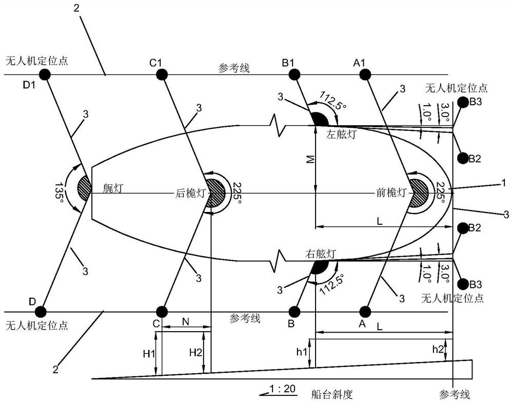
[0023] Such as figure 1 As shown, a method for inspection of ship navigation signal lights based on unmanned aerial vehicles, using unmanned aerial vehicles to inspect ship navigation signal lights, specifically includes the following steps:

[0024] 1) The specific position of the ship under construction, the horizontal dock or the inclined berth 1, draw the reference line 2 on both sides of the ship, and draw the angle line 3 of the navigation signal light according to the angle of the navigation signal light, where the angle line of the navigation signal light in the horizontal dock is different from the reference line Height difference, if the berth is inclined, the height difference of the intersection point needs to be calculated according to the slope of the berth;

[0025] Reference line 1 is based on the centerline of the hull, defin...


PUM


Abstract

A ship navigation signal lamp inspection method based on an unmanned aerial vehicle comprises the steps that reference lines at the two sides of a ship are drawn at the specific position of the ship under construction; the intersection point of the angle line and the reference line is the horizontal projection position of the unmanned aerial vehicle, the intersection points are drawn on the corresponding ground according to on-site lofting, and the intersection points A, A1, B, B1, B2, B3, C, C1, D and D1 are determined; the height value of each intersection point is determined according to the actual height of the navigation signal lamp; the intersection point and the height value are the accurate position of the unmanned aerial vehicle in the signal lamp inspection process; and a ship navigation signal lamp is turned on, the unmanned aerial vehicle is operated by a remote controller and flies to a pointed position, the angle adjustment position of the navigation signal lamp is determined through a video, the angle of the navigation signal lamp is adjusted according to the position of the unmanned aerial vehicle until the critical irradiation angle line of the navigation signal lamp coincides with the unmanned aerial vehicle, and the standard of qualified inspection is met. The unmanned aerial vehicle is used for inspection, and the method has the advantages of being high in efficiency, easy to operate, low in cost and high in safety.

Description

technical field [0001] The invention belongs to the field of ship inspection and relates to an inspection method for ship navigation signal lights based on an unmanned aerial vehicle. Background technique [0002] In the process of ship construction, some inspection links are essential, but the inspection will waste a lot of manpower and material resources, which is not conducive to reducing the construction cost. Especially for ships built on berths, the navigation signal lights must be inspected, angle adjusted, and plan modified after launching and before sea trial. At present, the following problems exist in the inspection process: [0003] 1. After the ship is launched, the general cycle is relatively long, which is not conducive to the inspection of navigation signal lights by drones, and the coordinate points cannot be confirmed; [0004] 2. Using the traditional method to inspect navigation signal lights requires the cooperation of tugboats to inspect one by one at...

Claims


Application Information

Patent Timeline
Patent Type & Authority Applications(China)
IPC IPC(8): G01R31/44G01M11/02B64C39/02
CPCG01R31/44G01M11/02B64C39/024B64U2101/00
Inventor 朱雨雷熊元元
Owner COSCO ZHOUSHAN SHIPYARD
Why Eureka
Try Eureka