Wide-angle scanning lens terminal antenna and scanning mode thereof

A terminal antenna and wide-angle scanning technology, which is applied in the direction of antennas and electrical components, can solve the problems of large volume of high-gain antenna array, inability of lens antenna array to perform fast beam scanning, and large number of channels to achieve high gain and high scanning angle. Big, flexible effects

Pending Publication Date: 2021-12-28
重庆两江卫星移动通信有限公司
View PDF0 Cites 1 Cited by
  • Summary
  • Abstract
  • Description
  • Claims
  • Application Information

AI Technical Summary

Problems solved by technology

[0003] The technical problem to be solved by the present invention is the cost problem caused by the large volume and large number of channels of the existing high-gain antenna array, and the problem that the existing single-feed lens antenna array cannot perform fast beam scanning. A new type of antenna array is proposed Based on the wide-angle scanning lens terminal antenna loaded with a phased feed, the lens antenna effectively integrates the lens unit with the traditional phased array. By changing the phase of the phased feed, the scanning function of the lens can be realized, which can not only effectively Increase the gain of the antenna, and also realize the wide-angle scanning of the lens antenna

Method used


Image

  • Wide-angle scanning lens terminal antenna and scanning mode thereof
  • Wide-angle scanning lens terminal antenna and scanning mode thereof
  • Wide-angle scanning lens terminal antenna and scanning mode thereof

Examples


Embodiment 1

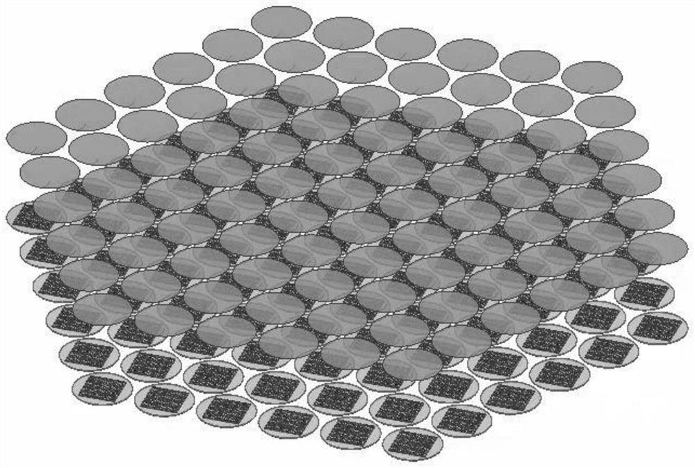
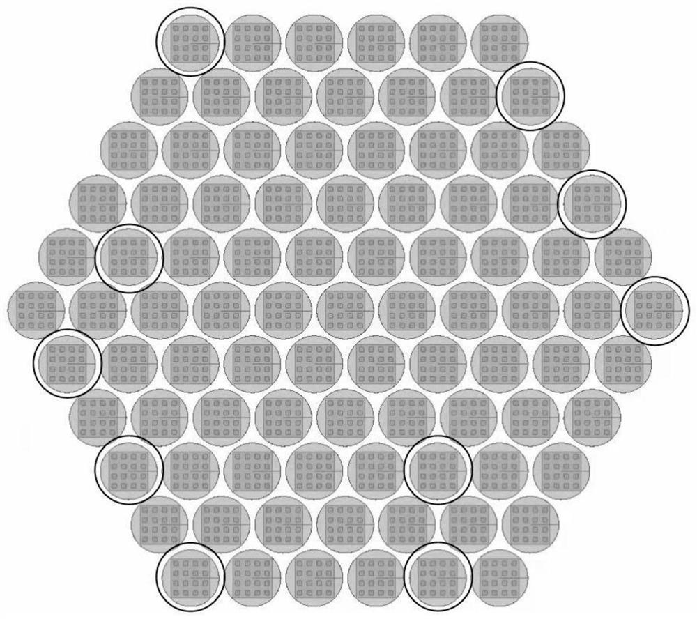
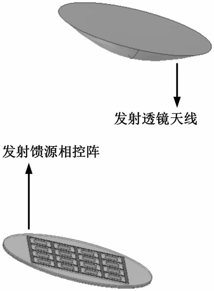
[0041] The invention discloses a wide-angle scanning lens terminal antenna, which includes a total array composed of several array elements with the same structure. The controlled feed source array is composed of 2N sub-arrays, and each sub-array is composed of N*N antenna elements, N∈[2,+∞]. There is a distance between the lens and the phased feed array, and they are supported by their respective supporting mechanisms. The supporting mechanism can be an existing technology such as a supporting plate. At the same time, the distance between the phased feed array and the lens is generally the same as that of the lens The focal length is equal, of course, will also be adjusted according to the actual situation.

[0042] In this embodiment, the lens is a plano-convex lens, and the convex surface of the lens faces the phased feed, and the plane of the lens radiates outward.

[0043] In this embodiment, the antenna unit includes a top layer, a middle layer and a bottom layer connec...

Embodiment 2

[0051] The present invention also has embodiment 2, a scanning mode of a wide-angle scanning lens terminal antenna, comprising the following steps:

[0052] S1. Giving equal-amplitude feeds to each of the antenna units in each of the phased feed arrays, and the phases of the antenna units in each of the sub-arrays are sequentially different by 90°, and the phase of each of the sub-arrays is set Same, obtain the normal pattern of the total array;

[0053] S2. Through the normal direction diagram of the total array combined with the reconfigurable lens antenna array grating lobe suppression technology based on the differential evolution algorithm, the array is comprehensively analyzed, and the phase of each lens unit (array element) when scanning the target scanning position is obtained. Information ψ i ;

[0054] S3, according to the phase information ψ of the lens unit (array element) i The relationship between the phase center of the phased feed array and the radiation cha...


PUM


Abstract

The invention relates to the field of lens antennas, and discloses a wide-angle scanning lens terminal antenna which comprises a total array composed of a plurality of array elements of the same structure, each array element comprises a lens and a phase control feed source array which are in one-to-one correspondence from top to bottom, each phase control feed source array is composed of 2N sub-arrays, each sub-array is composed of N * N antenna units, and N belongs to [2, + infinity]. The invention further discloses a scanning mode of the wide-angle scanning lens terminal antenna. According to the invention, high gain and large-angle scanning performance of the terminal antenna is realized through the plano-convex lens antenna structure based on the phased feed source, and compared with a traditional phased-array antenna and a traditional lens antenna, the terminal antenna has the effects of high flexibility, high gain, large scanning angle and the like.

Description

technical field [0001] The invention relates to the field of lens antennas, in particular to a wide-angle scanning lens terminal antenna and a scanning method thereof. Background technique [0002] The terminal antenna with tracking capability is one of the key components of the satellite communication system. In order to realize the automatic tracking capability of the antenna to the satellite, the wide-angle scanning capability of the terminal antenna is required. The phased array antenna is installed on the mobile terminal in the sea, land and air, and it is a common terminal system design for satellite tracking and communication. Using the traditional phased array technology with scanning capability, the wide-angle scanning function can be realized by controlling the phase information of each unit channel. However, when considering high-gain design, the number of elements in the antenna array will increase, and the corresponding feed network will become complex and larg...

Claims


Application Information

Patent Timeline
Patent Type & Authority Applications(China)
IPC IPC(8): H01Q15/02H01Q19/06
CPCH01Q15/02H01Q19/06
Inventor 冉普航曾凌钟开源罗超鸣刘金利第五健健向磊
Owner 重庆两江卫星移动通信有限公司
Why Eureka
Try Eureka