Cervical opening size monitoring device and method and application thereof
A technology of opening size and monitoring device, applied in application, telemetry patient monitoring, use of spectral diagnosis, etc., can solve problems such as cost reduction, and achieve the effect of improving imaging accuracy, low difficulty in implementation, and high imaging accuracy
- Summary
- Abstract
- Description
- Claims
- Application Information
AI Technical Summary
Problems solved by technology
Method used
Image

Examples
Embodiment 1
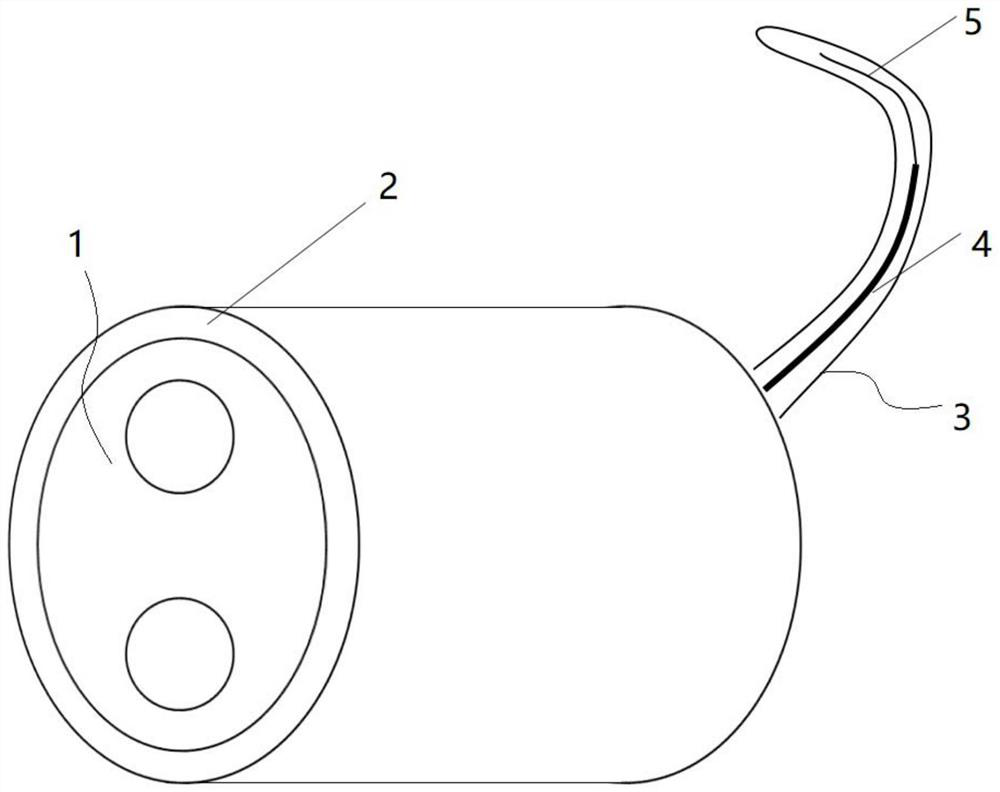
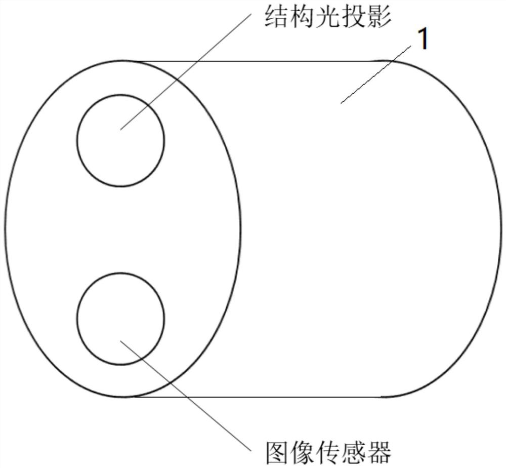
[0046] see Figure 1-3 , The cervical opening size monitoring device includes a terminal and a probe body 1 communicatively connected with the terminal, the probe body 1 and a disposable casing 2 covering the probe body 1, wherein the terminal is a mobile phone or a tablet or a computer. The probe body 1 adopts a waterproof shell, which is delicate and small in size and has good waterproof performance. It can be sterilized with alcohol after use, which is convenient for repeated use, and the disposable shell 2 can be replaced.
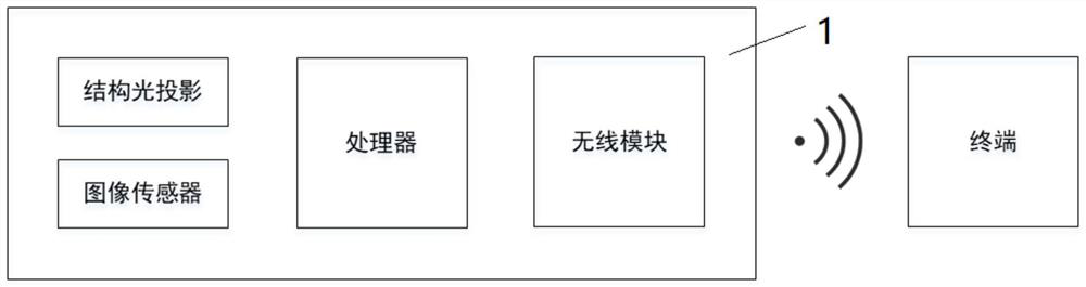
[0047] Specifically, the probe body 1 is provided with a structured light emitter, an image sensor for receiving light reflected from the structured light emitter, a processor for processing light signals received by the image sensor, and a wireless module. The module is used to send the light signal processed by the processor to the terminal, so that the terminal can generate and display the three-dimensional model of the cervical opening in real time...
Embodiment 2
[0056] see Figure 4-5 The difference between this embodiment and Embodiment 1 is that the TOF three-dimensional modeling technology is adopted, that is, the structured light emitter is replaced with an infrared laser pulse emitter. Among them, TOF in TOF three-dimensional modeling technology is the abbreviation of Time of Flight, also known as time-of-flight 3D imaging. As the name implies, it is to obtain the distance by measuring the flight time of light. It adopts CCD / CMOS imaging array combined with active infrared laser modulation technology. To obtain the depth information of the three-dimensional scene, the infrared laser pulse is continuously sent to the measured target, and then the sensor imaging array receives the reflected infrared laser pulse, and the distance information of the scene is obtained by measuring the phase delay between the emitted light pulse and the received light pulse , or another more popular explanation is Time of flight. The basic principle of...
Embodiment 3
[0059] see Figure 6-7 A method for monitoring the size of the opening of the cervix, using the aforementioned device for monitoring the size of the opening of the cervix, specifically comprising the following steps:
[0060] Insert the probe body 1 into the puerpera's vagina and adjust the position;
[0061] The structured light / infrared laser pulse emitter emits light, and the image sensor receives the reflected light signal and processes it by the processor, and then sends the processed light signal to the terminal through the wireless module;
[0062] The terminal generates and displays a three-dimensional model of the cervix in real time according to the light signal;
[0063] The terminal recognizes the cervical os according to the three-dimensional modeling of the cervix and calculates the size of the cervix;
[0064] The terminal displays the size of the opening of the cervix automatically or according to the user's request.
[0065] The above steps only give a basi...
PUM
 Abstract
Description
Claims
Application Information
 - R&D
- Intellectual Property
- Life Sciences
- Materials
- Tech Scout
- Unparalleled Data Quality
- Higher Quality Content
- 60% Fewer Hallucinations
Browse by: Latest US Patents, China's latest patents, Technical Efficacy Thesaurus, Application Domain, Technology Topic, Popular Technical Reports.
© 2025 PatSnap. All rights reserved.Legal|Privacy policy|Modern Slavery Act Transparency Statement|Sitemap|About US| Contact US: help@patsnap.com