Developing structure, stent and thrombus removal system
A rod and tail end technology, which is applied in the field of development structure, bracket and thrombus retrieval system, can solve the problem that the visibility effect is not ideal, and achieve the effect of increasing the far-end development effect, increasing the volume density and increasing the friction force
- Summary
- Abstract
- Description
- Claims
- Application Information
AI Technical Summary
Problems solved by technology
Method used
Image

Examples
Embodiment 1
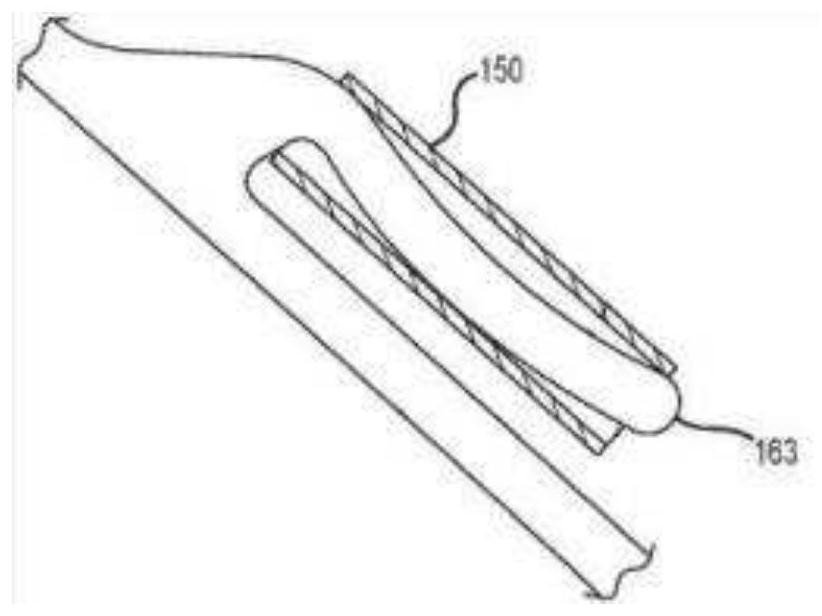
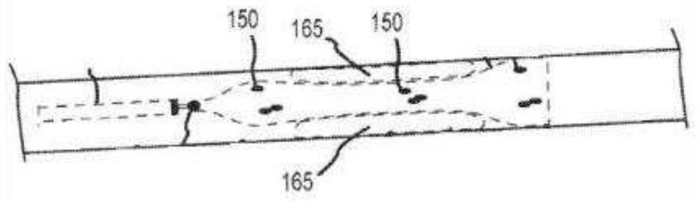
[0069] image 3 It shows a structural schematic diagram of the free rod connected with the probe rod at the distal end of the stent in the developing structure according to an embodiment of the present invention. Figure 4 A schematic structural view of a developing spring with a first tail end in the developing structure according to an embodiment of the present invention is shown. Figure 5 A schematic structural view of the bracket in the development structure of Embodiment 1 of the present invention is shown. Figure 6 A front view of a developing structure according to an embodiment of the present invention is shown. Figure 7 A schematic diagram showing a developing structure, a developing spring with a first tail end, and a rod portion according to an embodiment of the present invention. Figure 8 A schematic diagram showing a development structure, a development spring with a second tail end, and a rod portion according to an embodiment of the present invention is wo...
Embodiment 2
[0079] Figure 10 A schematic diagram of winding a developing spring and a rod portion having a first tail end and a second tail end in the developing structure according to Embodiment 2 of the present invention is shown. Figure 11 It shows the front view of the developing structure of Embodiment 2 of the present invention.
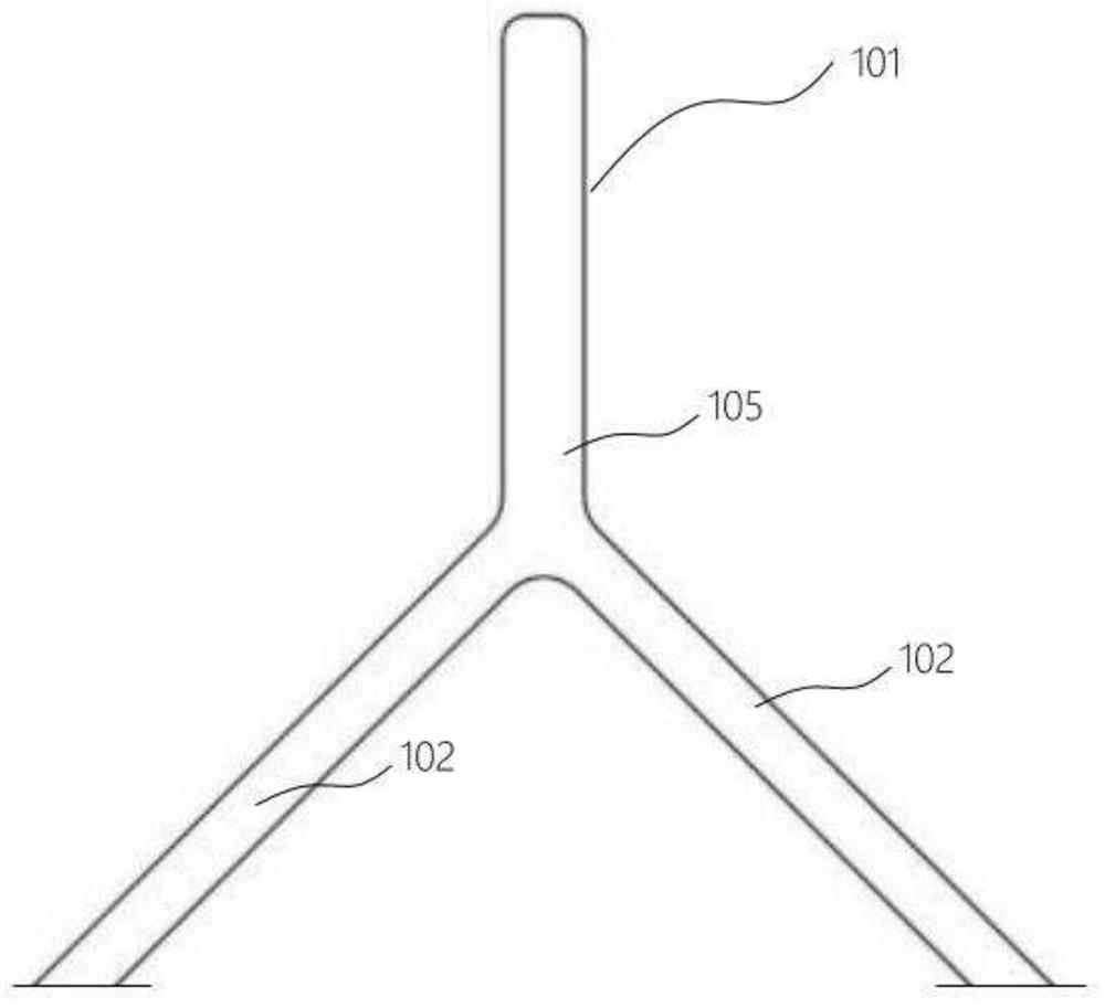
[0080] Please refer to Figure 10 and Figure 11 The structures of the rod portion 101 and the developing sleeve 2 in the second embodiment are the same as those in the first embodiment, and the rod portion 101 is located at the distal end portion 104 of the bracket 11. Preferably, the developing sleeve 2 in the developing structure of the second embodiment of the present invention is also a developing Spring, the developing spring is wound from a developing wire, but the structure of the filling part 3 is different from that of the first embodiment, wherein the filling part 3 is a filling wire and / or a polymer filler mixed with a developing material, ...
Embodiment 3
[0084] Figure 12 A top view of the developing structure of Embodiment 2 of the present invention is shown. Figure 13 A front view of the development structure of Embodiment 3 of the present invention is shown.
[0085] Please refer to Figure 12 and Figure 13 The structure of the rod portion 101 and the developing sleeve 2 in the developing structure provided in the third embodiment is the same as that in the first embodiment, and the rod portion 101 is located at the distal end 104 of the bracket 11. Preferably, the developing sleeve in the developing structure in the second embodiment of the present invention 2 is also a developing spring, which is wound from one developing wire, but the structure of the filling part 3 is different from that of Embodiment 1, wherein the filling part 3 is a filling wire and / or a polymer filler mixed with a developing material , the filling filaments include at least one or more of the extended developing filaments of the developing slee...
PUM
| Property | Measurement | Unit |
|---|---|---|
| The inside diameter of | aaaaa | aaaaa |
| Diameter | aaaaa | aaaaa |
| Length | aaaaa | aaaaa |
Abstract
Description
Claims
Application Information
 - R&D
- Intellectual Property
- Life Sciences
- Materials
- Tech Scout
- Unparalleled Data Quality
- Higher Quality Content
- 60% Fewer Hallucinations
Browse by: Latest US Patents, China's latest patents, Technical Efficacy Thesaurus, Application Domain, Technology Topic, Popular Technical Reports.
© 2025 PatSnap. All rights reserved.Legal|Privacy policy|Modern Slavery Act Transparency Statement|Sitemap|About US| Contact US: help@patsnap.com