Computer case processing surface paint spraying equipment with paint recycling structure

A computer case and surface processing technology, which is applied to spray devices, dispersed particle separation, chemical instruments and methods, etc., can solve the problems of inconvenient recycling, inconvenient deodorization, inconvenient cleaning, etc., to avoid waste and improve the effect of adsorbing odors. The effect of reducing the air velocity

Pending Publication Date: 2021-12-31
深圳市通强数控科技有限公司
View PDF0 Cites 0 Cited by
  • Summary
  • Abstract
  • Description
  • Claims
  • Application Information

AI Technical Summary

Problems solved by technology

[0006] The object of the present invention is to provide a computer case processing surface painting equipment with a paint recovery structure to solve the problems of inconvenient recycling, inconvenient deodorization and inconvenient cleaning proposed in the above background technology

Method used


Image

  • Computer case processing surface paint spraying equipment with paint recycling structure
  • Computer case processing surface paint spraying equipment with paint recycling structure
  • Computer case processing surface paint spraying equipment with paint recycling structure

Examples


Embodiment 1

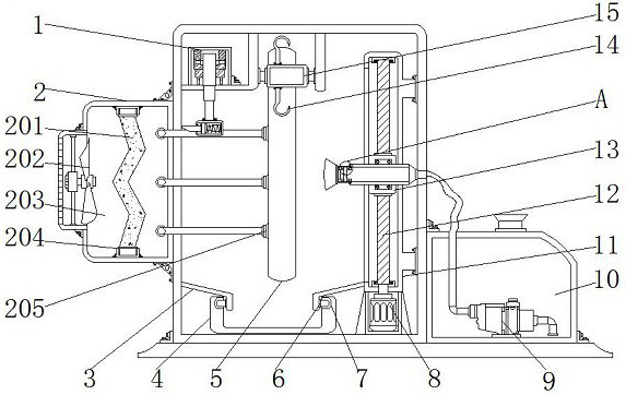
[0030] Example 1: See Figure 1-6 , a computer case processing surface painting equipment with a paint recovery structure, including a housing 16 and a bottom plate 17, and also includes a recovery mechanism 1 for easy recovery of paint, an adsorption mechanism 2 for avoiding odor pollution, and an installation structure for easy cleaning.

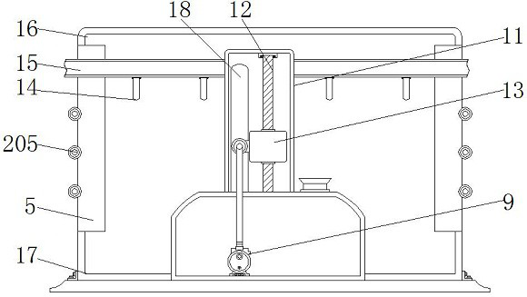
[0031] The top of base plate 17 is equipped with casing 16, and the two ends of casing 16 one side upper ends are all vertically provided with opening 5, and the middle position of casing 16 inside one side is vertically installed with fixed box 11, and fixed box 11 The bottom end of the housing 16 at the bottom is equipped with a drive motor 8, the model of which is YE2-132M1, and the output end of the drive motor 8 is vertically provided with a screw 12 extending to the inside of the fixed box 11 through a rotating shaft, and the screw The surface of the rod 12 is threaded with a rod block 13, and one end of the rod block 13 is installed...

Embodiment 2

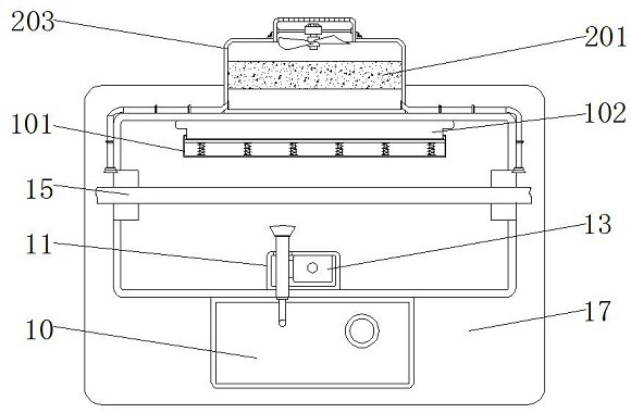
[0038] Embodiment 2: The recovery mechanism 1 comprises a recovery box 101, a scraper 102, a movable plate 103, a recovery spring 104 and a pneumatic telescopic rod 105, and the pneumatic telescopic rod 105 is installed on the inner top of the housing 16 on one side of the conveyor belt 15. The pneumatic telescopic rod The model of 105 can be XTL100, and the output end of the pneumatic telescopic rod 105 is equipped with a recovery box 101, and one side of the recovery box 101 is equipped with six recovery springs 104 at equal intervals, and the recovery box 101 on the side of the recovery spring 104 slides inside A movable plate 103 is connected, and a scraper 102 extending to the outside of the recovery box 101 is installed on one side of the movable plate 103 .

[0039] A slide block 6 is installed on one side of the bottom end of the swash plate 3 , and a chute 7 matched with the slide block 6 is provided at the upper ends of both sides of the collection tank 4 .

[0040] ...

Embodiment 3

[0041] Embodiment 3: adsorption mechanism 2 comprises activated carbon plate 201, negative pressure blower 202, adsorption box 203, slide groove 204 and suction head 205, and adsorption box 203 is installed in the middle position of housing 16 other sides, and adsorption box 203 Both the top and the bottom of one side of the interior are equipped with a sliding groove 204, and an activated carbon plate 201 is arranged inside the adsorption box 203 at one end of the sliding groove 204, and a negative pressure fan 202 is installed at the middle position of the side of the adsorption box 203 away from the housing 16. , the model of the negative pressure fan 202 can be HTF-I-3, three suction heads 205 are installed at equal intervals on both sides of the housing 16 on the side of the opening 5, and one side of the suction head 205 passes through the conduit and the adsorption box 203 Both ends are connected.

[0042] The shape of the activated carbon plate 201 is a side W shape, a...


PUM


Abstract

The invention discloses computer case processing surface paint spraying equipment with a paint recycling structure. The equipment comprises a shell and a bottom plate, the shell is installed at the top end of the bottom plate, openings are vertically formed in the two ends of the upper end of one side of the shell, and a fixing box is vertically installed in the middle of one side of the interior of the shell. A rod block is in threaded connection with the surface of a lead screw, a spraying pipe extending into the shell is installed at one end of the rod block, and a spraying cavity is formed in one end of the spraying pipe. An inclined plate is installed in the shell and located on one side of the fixing box, a collecting groove is formed in the bottom end, at the bottom end of the inclined plate, of the interior of the shell, and a hook is installed on the surface of a conveying belt. A paint box is installed at the top end of the bottom plate and located on one side of the shell, and a paint pump is installed on one side of the bottom end of the interior of the paint box. Through arrangement of a clamping groove and a clamping block, the spraying cavity can be conveniently and rapidly disassembled and assembled so that the interior of the spraying cavity can be conveniently cleaned, the situation that the spraying cavity is blocked by residual paint is avoided, and the spraying efficiency is guaranteed.

Description

technical field [0001] The invention relates to the technical field of computer case processing equipment, in particular to a computer case processing surface painting equipment with a paint recovery structure. Background technique [0002] With the development of society and the continuous development of science and technology in our country, computers have become an electronic product that can be seen everywhere in our lives. As a part of computer accessories, the main function of the chassis is to place and fix various computer accessories. The service life usually needs to be painted on its surface, but there are still many problems or defects in the existing computer case processing surface painting equipment. [0003] First, the traditional computer case processing surface painting equipment does not have a recovery structure when used, and the paint left after spraying cannot be recycled well, resulting in waste. [0004] Second, the traditional computer case process...

Claims


Application Information

Patent Timeline
Patent Type & Authority Applications(China)
IPC IPC(8): B05B14/41B05B15/55B05B13/04B05B13/02B01D53/04
CPCB05B14/41B05B15/55B05B13/041B05B13/0278B01D53/04Y02P70/10
Inventor 甄洁萍蔡伟祺刘荣轩
Owner 深圳市通强数控科技有限公司
Why Eureka
Try Eureka