
Automatic special clamp for steel piston machining

A special fixture, steel piston technology, used in manufacturing tools, workpiece clamping devices, metal processing equipment, etc., can solve the size deviation between the center of the piston cavity and the outer circle, long time for loading and unloading materials, and affecting the overall quality of the product. and other problems, to achieve the effect of improving clamping efficiency, improving one-time pass rate, and reducing product quality problems

Active Publication Date: 2021-12-31
BINZHOU BOHAI PRECISION MACHINERY +1
View PDF4 Cites 0 Cited by
  • Summary
  • Abstract
  • Description
  • Claims
  • Application Information

AI Technical Summary

Problems solved by technology

[0003] In the related technology, when processing the piston spigot, three claws are used to clamp the outer circle of the piston blank, which is easy to cause the center of the piston inner cavity and the outer circle to be easily generated when the piston outer circle is processed by the spigot positioning and other processes. Dimensional deviation will lead to uneven wall thickness of the piston and product weight error, which will affect the overall quality of the product; when processing the outer circle, top surface and combustion chamber of the piston, all adopt the mode of notch positioning and pin tensioning, and operate during manual clamping The operator needs to hold the pin in one hand and the piston in the other hand. The steel piston is heavy and difficult to operate; when the automatic line is clamped, it takes a long time to load and unload the material and pull the pin, and there is a certain failure rate

Method used


Image

  • Automatic special clamp for steel piston machining
  • Automatic special clamp for steel piston machining

Examples


Embodiment Construction

[0031] In order to understand the above-mentioned purpose, features and advantages of the present invention more clearly, the present invention will be further described in detail below in conjunction with the accompanying drawings and specific embodiments. It should be noted that, in the case of no conflict, the embodiments of the present application and the features in the embodiments can be combined with each other.

[0032] In the following description, many specific details are set forth in order to fully understand the present invention. However, the present invention can also be implemented in other ways different from those described here. Therefore, the protection scope of the present invention is not limited by the specific details disclosed below. EXAMPLE LIMITATIONS.

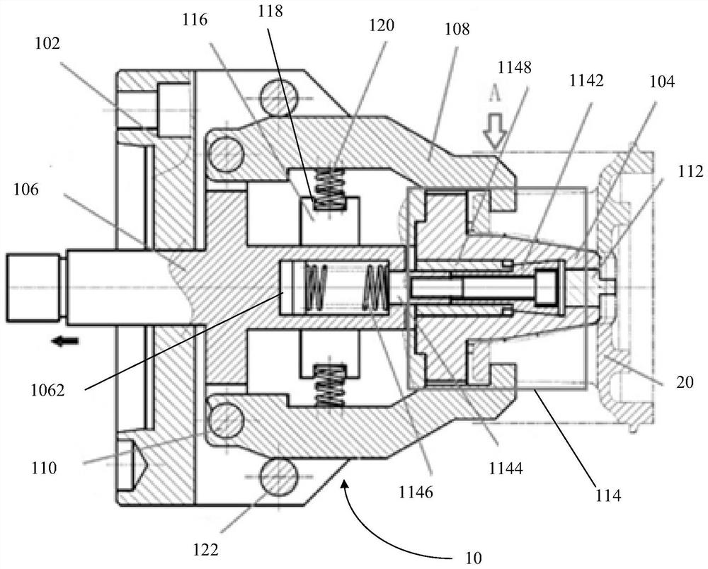
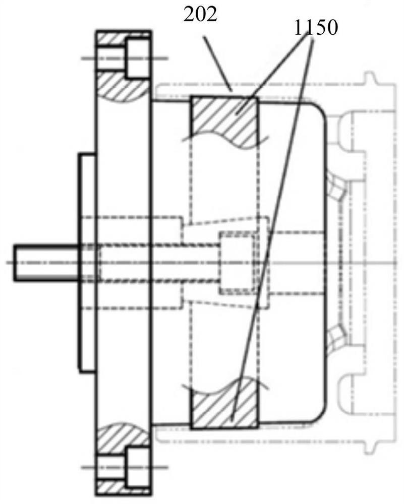
[0033] Combine below figure 1 and figure 2 An automatic special fixture for machining steel pistons according to an embodiment of the present invention will be described in detail.

[0034] Such ...


PUM


Abstract

The invention provides an automatic special clamp for steel piston machining. The automatic special clamp comprises a tool connecting disc, a positioning tire, a pull rod, a tensioning claw and an axial positioning block; the tool connecting disc and the positioning tire are connected and arranged in a matched mode, and the positioning tire is fixedly connected to one end of the tool connecting disc; the pull rod and the tensioning claw are connected and arranged in a matched mode, the pull rod and the tensioning claw are movably connected and arranged on the tool connecting disc through a fixing hinge pin, and the tensioning claw is located on the outer side of the positioning tire and enters a steel piston pin hole in an externally-embedded mode; and the axial positioning block is arranged at the end part of the positioning tire, and when the tensioning claw tensions a steel piston, the axial positioning block makes contact with an inner cavity of the steel piston. According to the technical scheme, the inner cavity of the piston is tensioned and positioned, and therefore, the uniform wall thickness of a skirt part can be fully guaranteed; the tensioning claw is clamped into the pin hole in an externally-embedded mode to lock a workpiece, and therefore, the firm clamping of the piston can be fully guaranteed; and multiple-procedure machining can be completed through one-time clamping, so that the automatic special clamp is very convenient to use for manual clamping and automatic machining.

Description

technical field [0001] The invention relates to the technical field of steel piston processing devices, in particular to an automatic special fixture for steel piston processing. Background technique [0002] With the release of national V and national VI standards for engines, the performance requirements for engine pistons are getting higher and higher. High explosion pressure, low fuel consumption, low noise and low emission have become the standard configurations of automobile engines, and the piston material has gradually replaced the existing aluminum alloy material with steel material, and the processing of steel piston is about to enter a period of mass production. The processing of steel piston includes the process of piston seam, piston outer circle, top surface and combustion chamber process, etc. [0003] In the related technology, when processing the piston spigot, three claws are used to clamp the outer circle of the piston blank, which is easy to cause the ce...

Claims


Application Information

Patent Timeline
Patent Type & Authority Applications(China)
IPC IPC(8): B23Q3/06B25B11/00
CPCB23Q3/062B25B11/00
Inventor 于志勇杨经立郭小鹏刘维娟张春明张志伟于明辉
Owner BINZHOU BOHAI PRECISION MACHINERY
Learn More