Automatic feeding and polishing device, production line with same and method

A technology of automatic feeding and material rack, which is applied in the direction of grinding drive device, parts of grinding machine tools, machine tools suitable for grinding workpiece edges, etc., which can solve problems such as affecting grinding efficiency.

Pending Publication Date: 2021-12-31
江苏宏宝优特管业制造有限公司
View PDF0 Cites 1 Cited by
  • Summary
  • Abstract
  • Description
  • Claims
  • Application Information

AI Technical Summary

Problems solved by technology

[0005] One of the purposes of the present invention is to solve the problem in the prior art that when grinding steel pipes, m...

Method used


Image

  • Automatic feeding and polishing device, production line with same and method
  • Automatic feeding and polishing device, production line with same and method
  • Automatic feeding and polishing device, production line with same and method

Examples


Embodiment 1

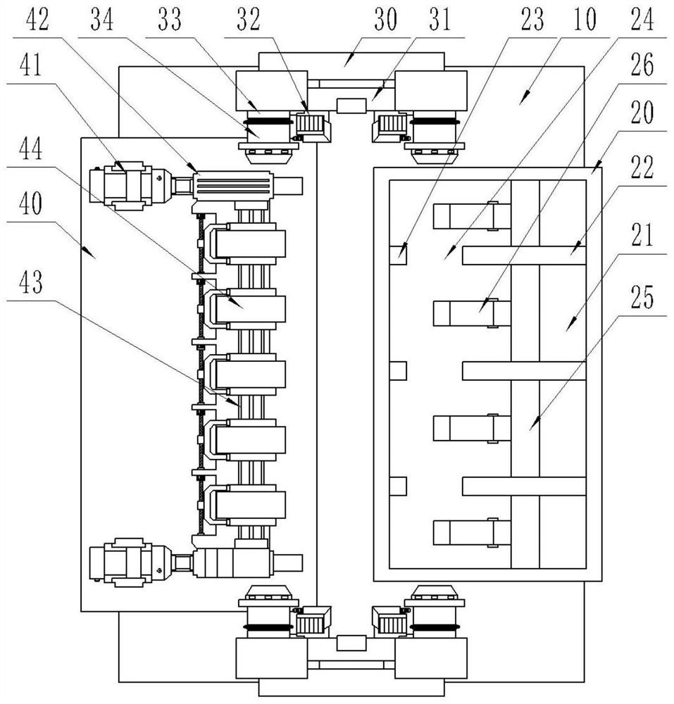
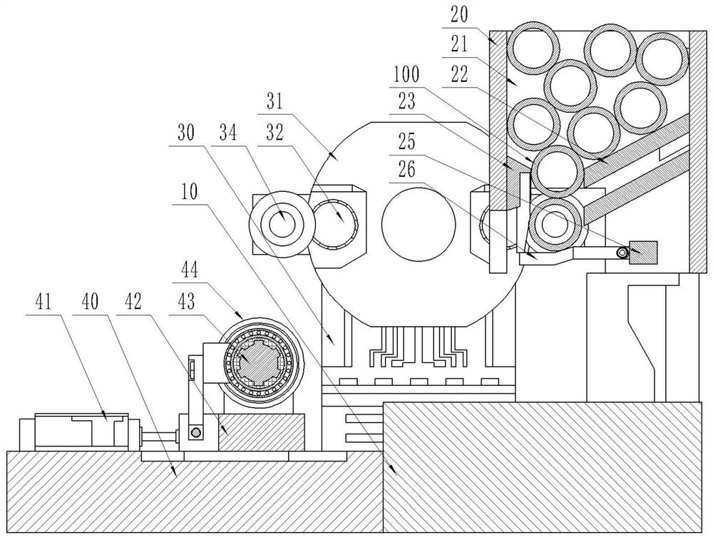
[0080] An automatic feeding grinding device, wherein, such as figure 1 , 2 As shown, a base 10 is included, and the base 10 includes: a loading frame 20 , a rotating and fixing mechanism 30 , and a grinding seat 40 .

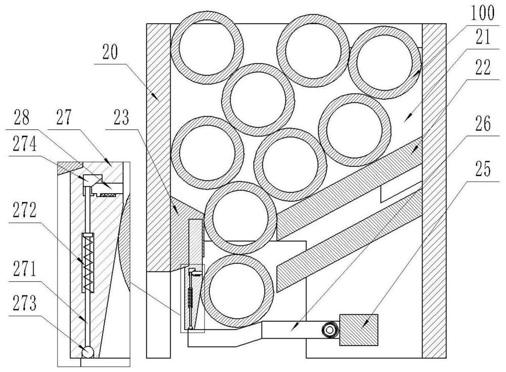
[0081] Such as figure 2 , 3 As shown, the loading rack 20 is installed on the right side of the base 10, the loading rack 20 has a storage space 21 for storing steel pipes to be polished, and the loading rack 20 also has: a right guide plate 22, a left guide plate 23, a fixed beam 25, movable baffle 26, limit baffle 27.

[0082] The right guide plate 22 is obliquely installed on the right side wall of the storage space 21 . The left guide plate 23 is obliquely installed on the left side wall surface of the storage space 21, and a blanking opening 24 for the steel pipe to be polished is formed between the left guide plate 23 and the right guide plate 22. The fixed beam 25 is located under the right guide plate 22 , and the fixed beam 25 is placed horizontal...

Embodiment 2

[0104] An automatic feeding and polishing device has the same characteristic structure and effect as that of Embodiment 1, wherein, such as Figure 9 , 10 As shown, there are a plurality of grinding wheels 44 distributed along the length direction of the steel pipe, and gaps exist between the plurality of grinding wheels 44 .

[0105] The main shaft 43 is provided with external teeth 431 , and a sliding sleeve 45 is provided between the main shaft 43 and the grinding wheel 44 . The sliding sleeve 45 has tooth slots matching the external teeth 431 , and the external teeth 431 are embedded in the tooth slots.

[0106] Both sides of the sliding sleeve 45 are connected with bearings 46 , the left side of the bearing 46 is connected with a connecting plate 47 , and the connecting plate 47 is threadedly connected with a transmission screw 48 .

[0107] It is found in the actual grinding of the steel pipe by the grinding wheel 44 that when the grinding wheel 44 adopts an integral st...

Embodiment 3

[0111] A production line, which has the automatic feeding and polishing device of the first or second embodiment.

[0112] Such as Figure 8 As shown, the upper left side of the grinding seat 40 is provided with a mechanical rod 50, the mechanical rod 50 is used to hook the polished steel pipe, the left side of the mechanical rod 50 is provided with a transport line 60, and the transport line 60 is used to receive the Steel Pipe.

[0113] After the steel pipe is polished, start the telescopic cylinder 41 to drive the emery wheel 44 to reset, and then start the rotating disk 31 to drive the polished steel pipe to rotate to the left side. At this time, the mechanical rod 50 is driven to rotate, so that the mechanical rod 50 hooks the steel pipe and stops turning to the electromagnet. 331 power supply, so that the clamping head 34 resets under the action of the pressure spring, and continue to rotate the mechanical rod 50, so that the mechanical rod 50 pushes the steel pipe to t...


PUM


Abstract

The invention discloses an automatic feeding and polishing device and relates to the technical field of steel pipe polishing. The automatic feeding and polishing device comprises a feeding frame, a rotary fixing mechanism and a polishing seat. Steel pipes to be polished are placed in the feeding frame in a centralized mode, the single steel pipe is guided into a preset position of the bottom of a discharging opening through a right or left guide plate of the feeding frame, then the steel pipes at the bottom of the discharging opening are clamped in a telescopic mode through a clamping head of the rotary fixing mechanism, and the steel pipes are moved to the polishing seat to be rotationally polished. When the steel pipes at the bottom of the discharging opening move out of the discharging opening, a movable baffle on the side of the discharging opening is stressed to rotate, so that a gravity ball pulls a pressure head to extrude a barrier plate to extend out to limit the steel pipe on the discharging opening to fall into the bottom of the discharging opening, and the barrier plate can be reset only after the movable baffle is reset, and finally the steel pipe on the discharging opening falls into the bottom of the discharging opening. By means of the simple structure, the rotary fixing mechanism can move the steel pipes to be polished into the polishing seat one by one to be polishing, automatic feeding, clamping and polishing operation is achieved, and the polishing efficiency is greatly improved.

Description

technical field [0001] The invention relates to the technical field of steel pipe grinding, in particular to an automatic feeding and grinding device. Background technique [0002] Steel pipes are used to transport fluids and powdery solids, exchange heat, and manufacture mechanical parts and containers. It is also a kind of economical steel. The development of steel pipe production technology began with the rise of the bicycle manufacturing industry, the development of petroleum in the early 19th century, the manufacture of ships, boilers, and aircraft during the two world wars, the manufacture of thermal power boilers after the Second World War, the development of the chemical industry and Drilling, production and transportation of oil and natural gas have strongly promoted the development of steel pipe industry in terms of variety, output and quality. [0003] As a pipeline for transportation, steel pipes must be polished. The first reason is that the surface finish is v...

Claims


Application Information

Patent Timeline
IPC IPC(8): B24B5/04B24B5/35B24B27/033B24B9/04B24B41/02B24B41/00B24B41/06B24B47/12B24B1/00
CPCB24B5/04B24B5/35B24B5/355B24B27/033B24B9/04B24B41/02B24B41/005B24B41/062B24B47/12B24B1/00
Inventor 朱剑峰仲蔡希王君梅
Owner 江苏宏宝优特管业制造有限公司
Why Eureka
Try Eureka