Drilling device for breathable safety helmet based on multi-directional fixing
The technology of a drilling device and a fixing device is applied in the field of drilling devices for breathable safety helmets, which can solve the problems of movement of safety helmets, inclination of drilling holes, failures, etc., so as to improve the clamping effect, facilitate subsequent cleaning, and improve safety. Effect
- Summary
- Abstract
- Description
- Claims
- Application Information
AI Technical Summary
Problems solved by technology
Method used
Image
Examples
Embodiment 1
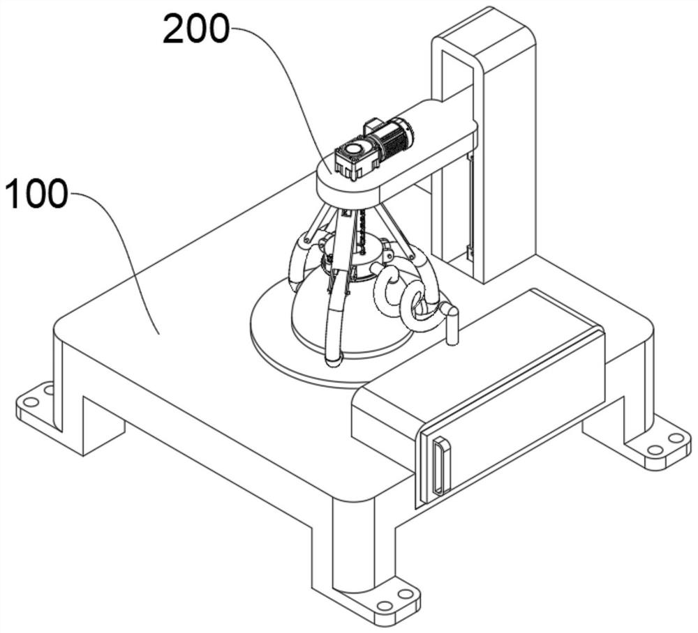
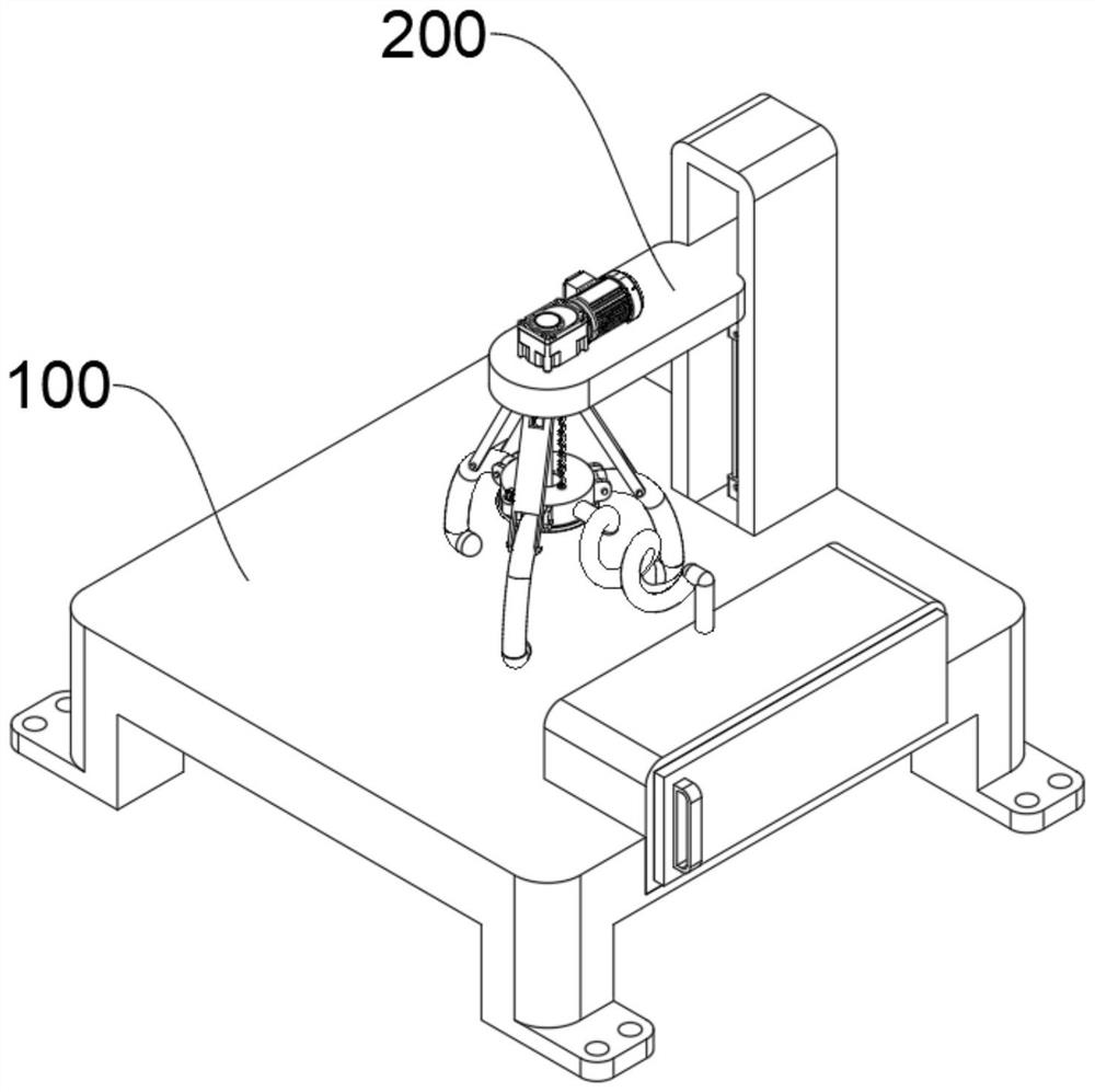
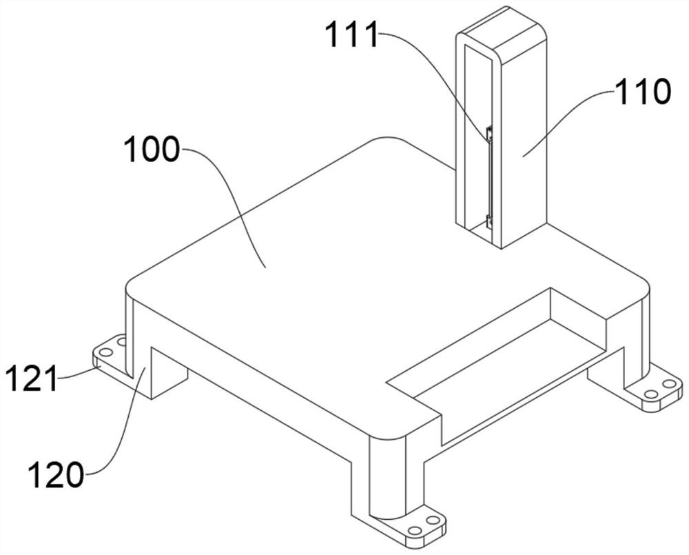
[0042] see Figure 1-Figure 7 As shown, the present embodiment provides a drilling device based on a multi-directional fixed breathable safety helmet, including a support plate 100 and a fixed drilling mechanism 200 above the support plate 100. The edge of the support plate 100 is provided with a lifting frame 110, and the lifting frame 110 An electric push rod 111 is embedded in the bottom of the cavity.
[0043] In order to improve the support stability, the bottom of the support plate 100 is provided with support legs 120 near the four corners, and the bottom of the support legs 120 is provided with a stabilizing plate 121. The stabilizing plate 121 can increase the contact area with the ground, improve the frictional force, and avoid slipping, so that The four support legs 120 support the support plate 100 more stably.
[0044] The fixed drilling mechanism 200 at least includes:
[0045]Lifting plate 210, one end of lifting plate 210 is slidingly arranged inside lifting ...
Embodiment 2
[0053] Considering the wear caused by the rigid extrusion of the bottom of the gripping rod 224 and the sliding sleeve 222 against the outer wall of the helmet, the difference between this embodiment and Embodiment 1 is that, please refer to Figure 8 shown, where:
[0054] In order to improve the clamping effect of the clamping rod 224 and avoid clamping wear, the end of the clamping rod 224 is provided with a chute 2241, the end of the chute 2241 is provided with a rubber head 2242, and the end of the rubber head 2242 is connected with a slide bar 2243. The rod 2243 is slidably arranged inside the chute 2241, and a sliding spring 2244 is fixedly connected between the sliding rod 2243 and the end of the inner cavity of the chute 2241, so that the sliding spring 2244 can be compressed when the end of the gripping rod 224 is attached to the outer wall of the safety helmet. , under the elastic force of the sliding spring 2244, not only the clamping effect can be improved, but at...
Embodiment 3
[0057] Considering that the dust attached to the inner wall of the cavity 2220 is inconvenient to clean, and it is easy to cause blockage for a long time, the difference between this embodiment and Embodiment 1 is that, please refer to Figure 9-Figure 10 shown, where:
[0058] A turntable 2221 is installed inside the cavity 2220. The bottom of the turntable 2221 is provided with a brush plate 2225. The outer surface of the brush plate 2225 is provided with a plurality of brushes 2226. The ends of the brushes 2226 are attached to the inner wall of the cavity 2220 to make the turntable 2221 rotate. Inside the cavity 2220, the brush plate 2225 is driven to rotate inside the cavity 2220, so that the brush 2226 sticks to the inner wall of the cavity 2220 for brushing, which is convenient for brushing off the attached impurities and subsequent cleaning.
[0059] In order to improve the degree of automation, the outer wall of the turntable 2221 is provided with a cam 2222, and the o...
PUM
 Abstract
Description
Claims
Application Information
 - R&D
- Intellectual Property
- Life Sciences
- Materials
- Tech Scout
- Unparalleled Data Quality
- Higher Quality Content
- 60% Fewer Hallucinations
Browse by: Latest US Patents, China's latest patents, Technical Efficacy Thesaurus, Application Domain, Technology Topic, Popular Technical Reports.
© 2025 PatSnap. All rights reserved.Legal|Privacy policy|Modern Slavery Act Transparency Statement|Sitemap|About US| Contact US: help@patsnap.com


