Cellular cluster multi-rotor unmanned aerial vehicle structure and control method thereof

A technology of multi-rotor UAV and control method, which is applied in the field of honeycomb cluster multi-rotor UAV structure and its control, can solve problems such as increased transportation and storage costs, GPS positioning system failure, motor propeller damage, etc., to reduce Transportation and storage costs, reduced transportation costs, and the effect of ensuring stability

Pending Publication Date: 2021-12-31
上海千机创新文旅科技集团有限公司
View PDF0 Cites 1 Cited by
  • Summary
  • Abstract
  • Description
  • Claims
  • Application Information

AI Technical Summary

Problems solved by technology

[0003] 1. When changing different mission vehicles or needing to increase the flight time, it is necessary to redesign another multi-rotor UAV individual flight performance, which increases a lot of research and development costs, including capital costs, time ,Labor costs;
[0004] 2. When an individual UAV performing a flight mission fails during the preparation phase or the flight phase, such as insufficient power, damage to the motor or propeller, or failure of the GPS positioning system, etc., the aircraft must be replaced, returned in an emergency, or forced to land on the spot. Operation, the flight mission was forced to be interrupted;
[0005] 3. Large-load multi-rotor UAVs are usually relatively large, and their mechanical structures are relatively complicated. Long-distance transportation will increase transportation and storage costs

Method used


Image

  • Cellular cluster multi-rotor unmanned aerial vehicle structure and control method thereof
  • Cellular cluster multi-rotor unmanned aerial vehicle structure and control method thereof
  • Cellular cluster multi-rotor unmanned aerial vehicle structure and control method thereof

Examples


Embodiment approach

[0053] Assume that the take-off weight of the honeycomb UAV is 1kg, the effective load weight is 1kg, and the regular flight time is 20 minutes.

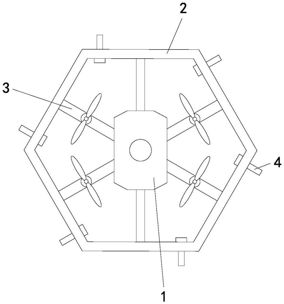
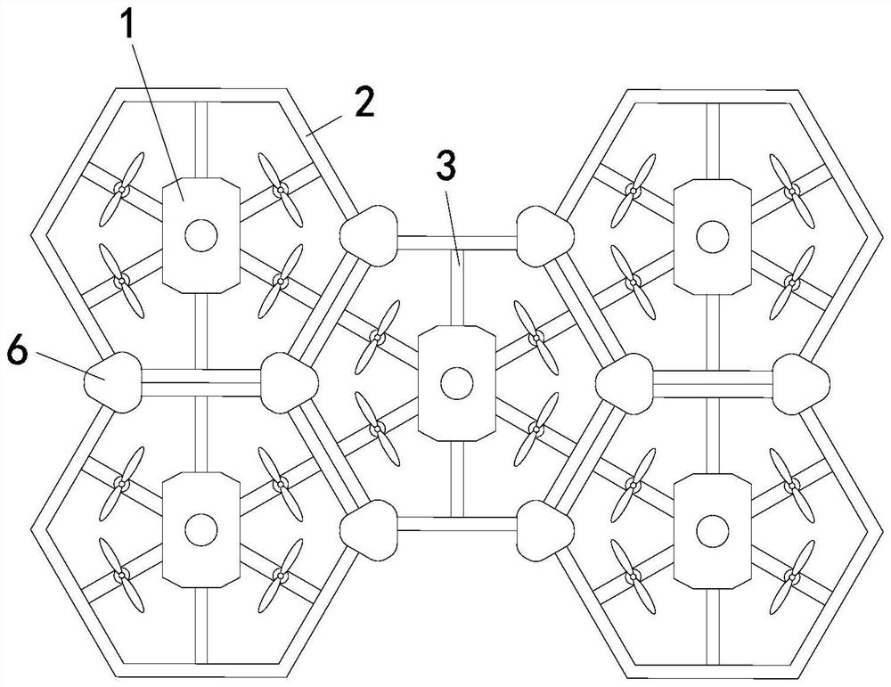
[0054] Determine the flight mode of the UAV: ​​for example, the weight of the task vehicle is 2kg, and the flight time is 10 minutes. In order to meet the weight requirements of the mission vehicle, the honeycomb hexacopter mode is selected. This mode consists of 7 honeycomb UAVs to form a six-rotor mode, one of which is the master and 6 are adjacent slaves. The theoretical loading weight can reach 7kg, which already meets the weight of the task vehicle.

[0055] Power redundancy setting: Assuming that one of the slaves loses power in the six-rotor mode, in order to maintain the flight stability of the honeycomb cluster, the slave on the opposite corner of the lost power will also suspend power output. At this time, the remaining 5 UAVs individually output power, the effective load is reduced to 5kg, and the overall mounted weight ...


PUM


Abstract

The invention relates to a honeycomb cluster multi-rotor unmanned aerial vehicle structure and a control method thereof. The honeycomb cluster multi-rotor unmanned aerial vehicle structure comprises a plurality of unmanned aerial vehicle bodies, a frame is erected on each unmanned aerial vehicle body, the frames are polygonal and surround the outer sides of the unmanned aerial vehicle bodies, and the inner sides of the frames are connected with the unmanned aerial vehicle bodies through connecting rods; the frames are further provided with fixing mechanisms, and the fixing mechanisms are used for enabling the frames to be detachably connected, so that the multiple unmanned aerial vehicle bodies are combined with one another and fly synchronously. When one of the unmanned aerial vehicles fails, the control right and real-time flight data are transferred, and whether the power failure is lower than the power redundancy setting is judged, so that a homeward voyage program is executed or a preset route task is continued. According to the honeycomb cluster multi-rotor unmanned aerial vehicle structure, through mutual superposition of a plurality of individual unmanned aerial vehicles with the same performance, the flight performance is improved, the loading capacity, the endurance time and the error-tolerant rate of a redundant system can be improved, and the research and development cycle and cost are greatly reduced.

Description

technical field [0001] The invention relates to the technical field of unmanned aerial vehicle flight, in particular to a honeycomb cluster multi-rotor unmanned aerial vehicle structure and a control method thereof. Background technique [0002] At present, in the multi-rotor UAV industry, the flight performance of the individual has basically been determined at the beginning of the design, including the number of rotors, flight time, and load capacity, to complete fixed flight tasks. This independent individual multi-rotor UAV has the following disadvantages: [0003] 1. When changing different mission vehicles or needing to increase the flight time, it is necessary to redesign another multi-rotor UAV individual flight performance, which increases a lot of research and development costs, including capital costs, time ,Labor costs; [0004] 2. When an individual UAV performing a flight mission fails during the preparation phase or the flight phase, such as insufficient pow...

Claims


Application Information

Patent Timeline
Patent Type & Authority Applications(China)
IPC IPC(8): B64C37/02B64C27/08B64C1/06G05D1/10
CPCB64C37/02B64C27/08B64C1/061G05D1/104B64U10/10B64U2201/102
Inventor 张海山黄梓坤杜金程郑奕航
Owner 上海千机创新文旅科技集团有限公司
Why Eureka
Try Eureka