Trenching assembly of chain type trencher

A trenching machine and chain technology, applied in the field of trenching components, can solve the problems of not being able to dig grooves specially, increase product cost, and wear blades too fast, and achieve the effects of improving work efficiency, efficiency and quality.

Active Publication Date: 2021-12-31
浙江宝通机械制造有限公司
View PDF5 Cites 1 Cited by
  • Summary
  • Abstract
  • Description
  • Claims
  • Application Information

AI Technical Summary

Problems solved by technology

[0003] 1. The service life of the blade when digging grooves is much lower than the service life of parts such as chains, but in this chain, the blade and the chain are fixed together by welding. When the blade needs to be replaced, the chain can only be replaced as a whole , there is the disadvantage of high replacement cost, and when corresponding to different widths of ravines, it is necessary to replace chains of different widths, which not only increases product costs but also brings great inconvenience to construction
[0004] 2. Existing trenching machines cannot carry out special excavation grooves according to different lands, that is, the same blade is used for soft soil and hard body, resulting in too slow slotting in soft soil, and too fast wear of the blade in hard soil technical issues

Method used


Image

  • Trenching assembly of chain type trencher
  • Trenching assembly of chain type trencher
  • Trenching assembly of chain type trencher

Examples


Embodiment 1

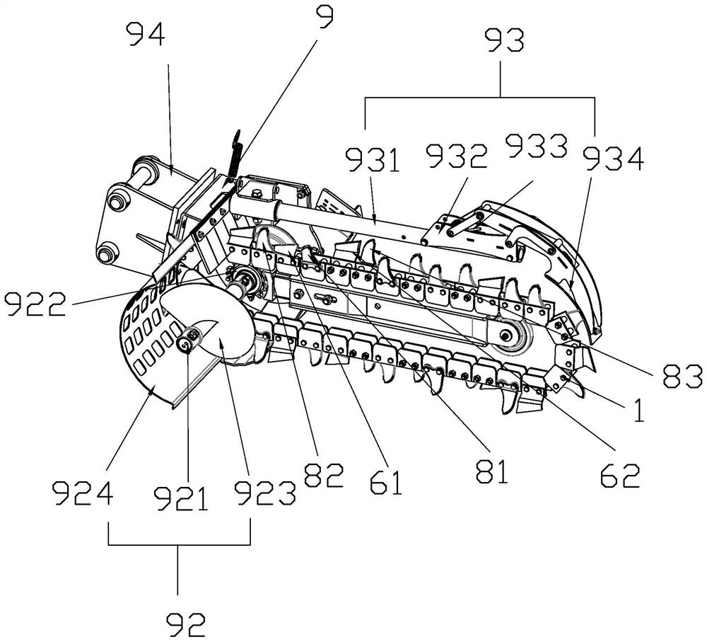
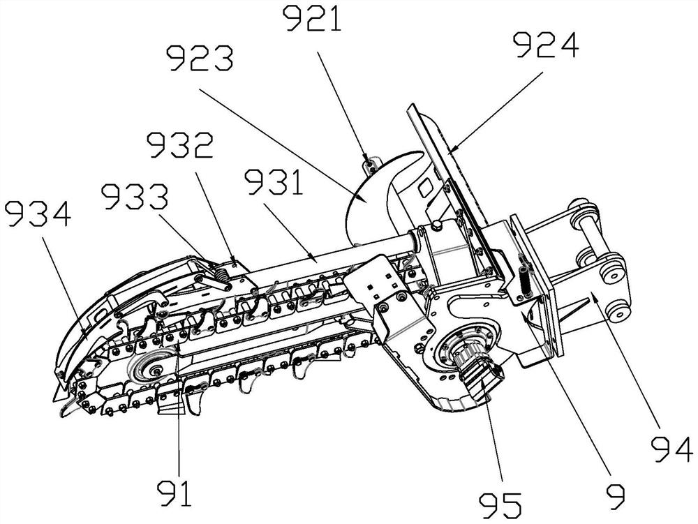
[0039] Such as Figure 1-Figure 14As shown, a ditching assembly of a chain trencher includes a frame 9, a cutter chain 91, a spiral soil removal device 92 and a soil clearing scraper device 93, and one end of the frame 9 is provided for connecting with the ditcher. Connected mounting base 94, the other end is provided with the driving guide wheel device that drives cutter chain and spiral earth moving device to rotate, and described driving guide wheel device comprises the drive motor 95 that is arranged on frame 9 one side, the output end of drive motor 95 An output shaft 921 is provided to drive the screw soil removal device 92 to work. The output shaft 921 is provided with a sprocket 922, and drives the cutter chain 91 to rotate through a chain transmission. Above, and connected with the frame 9 through the big arm 931, the cutter chain 91 is vertically arranged with the screw soil removal device 92, and the cutter chain 91 is sequentially combined by several groups of circ...

Embodiment 2

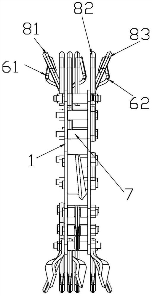
[0042] Such as Figure 10 , Figure 11 , Figure 12 , Figure 14 As shown, when trenching on soft ground, the trenching tooth group includes a left soil drilling cup tooth 61 and a right soil drilling cup tooth 62, and the left soil drilling cup tooth 61 is arranged on the left side of the outer chain plate 2. On the bolt 3 and one end extends to the outside of the outer link plate 2 to form a left arc plate 611, and the right drilling cup tooth 62 is arranged on the bolt 3 on the right side of the outer link plate 2 and one end extends to the outside of the outer link plate 2 to form a right arc plate 621, the bolt 3 between the two outer chain plates 2 can be loaded with a left soil drilling cup tooth 61 or a right drilling soil cup tooth 62, and the left soil drilling cup tooth 61 and the right drilling soil cup tooth 62 are respectively along the chain The length direction is staggered, and one end of the bolt 3 corresponding to the left drilling cup tooth 61 or the rig...

Embodiment 3

[0046] Such as Figure 5-Figure 9 , Figure 13 As shown, when trenching on hard or frozen ground, the set of trenching teeth includes a left trenching tooth 81, a middle trenching tooth 82 and a right trenching tooth 83, and the left trenching tooth 81 is set outside On the bolt 3 on the left side of the chain plate 2 and one end extends to the outside of the outer chain plate 2 to form a left blade 811, the middle groove tooth sleeve 82 is arranged on the bolt 3 in the middle of the two outer chain plates 2 and one end is vertically outward Extend to form the middle knife wing 821, the right trenching tooth 83 is sleeved on the bolt 3 on the right side of the outer chain plate 2 and one end extends to the outside of the outer chain plate 2 to form a right knife wing 831, the left trenching tooth 81, the middle digging The groove teeth 82 and the right groove teeth 83 are respectively staggered along the length direction of the chain, and one end of the bolt 3 corresponding t...


PUM


Abstract

The invention relates to a trenching assembly of a chain type trencher. Trenching tooth sets are arranged on a cutter chain of the trenching assembly, the trenching tooth sets of different specifications can be conveniently replaced through a first mounting structure, then grooves of different specifications can be rapidly matched, after the trenching tooth sets are abraded, the trenching tooth sets only need to be detached and replaced with new trenching tooth sets, then the trenching tooth sets can be directly used, a chain mounting block does not need to be replaced, the construction cost is reduced, when trenching is carried out on soil with different hardness, different chain units are arranged, stress is more uniform, abrasion is smaller, efficiency is higher, and then the trenching assembly adapts to different land conditions. With adoption of a soil cleaning scraping plate device, accumulation of covering soil after trenching can be reduced, and the quality of a trench is improved; with adoption of a spiral soil discharging device, cut soil returning into the trench can be reduced, and the working efficiency and the quality of the trench are improved; meanwhile, dug soil is accumulated beside the trench through the spiral soil discharging device, and backfilling after construction is facilitated.

Description

technical field [0001] The invention relates to the field of ditching machines, in particular to a ditching assembly of a chain type ditching machine. Background technique [0002] In the prior art, before conventional laying of pipelines, manual or mechanical methods are mostly used to dig and groove. Among them, the trencher is one of the main types of construction machinery, and it is a trenching machine used in earthwork construction. It is widely used. It is used in the construction of farmland water conservancy, the laying of communication cables and oil pipelines, municipal construction and military engineering, etc. The functions of the trencher and the excavator have many similarities. Both of them have the functions of entering soil (soil or rock), crushing soil and taking soil. The advantages of the trencher are continuous operation, high construction efficiency, and small surface damage. It is especially suitable for laying pipelines. Even in hard geological con...

Claims


Application Information

Patent Timeline
Patent Type & Authority Applications(China)
IPC IPC(8): E02F5/06E02F5/14E02F5/30E02F9/00E02F9/28
CPCE02F5/06E02F5/14E02F5/305E02F9/00E02F9/28
Inventor 毛鹏程吴皓亮
Owner 浙江宝通机械制造有限公司
Why Eureka
Try Eureka