Intelligent oil pipe lifting and pushing device for minor repair operation

A technology for pushing devices and oil pipes, which is applied in the direction of drilling pipes, casings, and drilling equipment. It can solve the problems that the oil pipe automatic discharge device occupies a large area, is not suitable for minor repair operations, and is not easy to install in place. It improves labor efficiency and is easy to install. Install in place, reduce the effect of labor intensity

Pending Publication Date: 2021-12-31
PETROCHINA CO LTD
View PDF7 Cites 0 Cited by
  • Summary
  • Abstract
  • Description
  • Claims
  • Application Information

AI Technical Summary

Problems solved by technology

[0005] However, the above oil pipe automatic discharge device occupies a large area, and the minor repair operation site is relatively small. It will be difficult to place the device itself when it enters the operation site, and it is not easy to install it in place. Therefore, it is not suitable for minor repair operations. Therefore, further research and design are needed. Developed an intelligent oil pipe lifting and pushing device for minor repair operations

Method used


Image

  • Intelligent oil pipe lifting and pushing device for minor repair operation
  • Intelligent oil pipe lifting and pushing device for minor repair operation
  • Intelligent oil pipe lifting and pushing device for minor repair operation

Examples


Embodiment 1

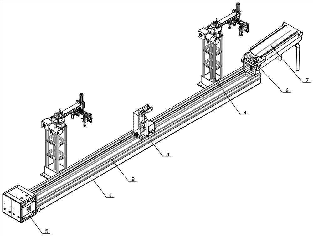
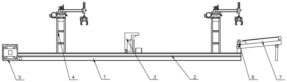
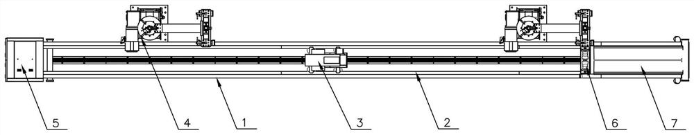
[0035] Such as Figure 1 to Figure 8 As shown, this embodiment provides an intelligent oil pipe lifting and pushing device for minor repair operations. The intelligent oil pipe lifting and pushing device includes a base 1, wherein, the base 1 is provided with a track 2, and the track 2 is provided with a lifting and pushing mechanism 3 that can slide along the track 2, and the same side of the base 1 is provided with at least two A grasping mechanism 4, the rear end of the base 1 is provided with a PLC controller 5, the front end of the base 1 is provided with a righting roller mechanism 6 perpendicular to the base 1, and the righting roller mechanism 6 is rotatably connected with a folding bracket 7, and the folding bracket 7 In the case of unfolding, it extends forward along the base 1, and the folding bracket 7 is arranged obliquely upwards from the back to the front. The folding bracket 7 can be placed on the top surface of the base 1 when it is folded, and the PLC control...

Embodiment 2

[0043] On the basis of Embodiment 1, this embodiment further explains the straightening roller mechanism 6 , the folding bracket 7 , and the lifting and pushing mechanism 3 .

[0044] The righting roller mechanism 6 includes a connecting bracket 61 perpendicular to the base 1, a Y-shaped roller bracket 62 is arranged on the connecting bracket 61, two righting rollers 63 are arranged on the Y-shaped roller bracket 62, and a V is formed between the two righting rollers 63. shaped notch, which can be better fixed when the oil pipe slides, and avoids the direction to be skewed or even dropped. The bottom of the righting roller 63 is provided with a screw assembly 64 for adjusting the height of the righting roller 63. The screw assembly 64 runs through the Y-shaped roller bracket 62 and The connecting bracket 61 is connected to the base 1 , and the folding bracket 7 is rotatably connected to the connecting bracket 61 . It should be noted that the Y-shaped roller bracket 62 and the ...

Embodiment 3

[0051] On the basis of Embodiment 1, this embodiment further describes the grasping mechanism 4 . Take the lengthwise direction of the base 1 as the X-axis direction, take the width direction of the base 1 as the Y-axis direction, and take the direction perpendicular to the base 1 as the Z-axis direction. The grabbing mechanism 4 includes a Z-axis support 41. The top of the Z-axis support 41 is connected to a telescopic X-axis support arm 43 through a horizontal rotation structure 42. The front end of the X-axis support arm 43 is provided with a liftable Y-axis support arm 44. At least two pairs of grasping grippers 45 are arranged on the Y-axis support arm 44 , the horizontal rotating structure 42 is driven by a rotary stepping motor 46 , and the grasping grippers 45 are driven by a grasping stepping motor 47 .

[0052] When the grasping mechanism 4 is required to grab the oil pipe and put it on the oil pipe support on the side, the rotating stepper motor 46 drives the X-axis...


PUM


Abstract

The invention discloses an intelligent oil pipe lifting and pushing device for minor repair operation, relates to the technical field of oil pipe arrangement devices, and solves the technical problem that an oil pipe arrangement device in the prior art is not easy to install in place when entering a minor repair operation site. The intelligent oil pipe lifting and pushing device comprises a base, a track, a lifting and pushing mechanism, a grabbing mechanism, a PLC, a centralizing roller mechanism and a folding support. According to the intelligent oil pipe lifting and pushing device for minor repair operation, the intelligent oil pipe lifting and pushing device is divided into the long base and the short folding support, can well adapt to the geomorphic characteristics of the geographical environment of a well site, can be conveniently placed in a small site, can be easily installed in place and can be conveniently transported after being folded; the automation degree is high, the labor intensity can be effectively reduced, the labor efficiency is improved, and the safety risk is reduced.

Description

technical field [0001] The present invention relates to the technical field of oil pipe arranging devices, and more specifically relates to the technical field of oil pipe lifting and pushing devices. Background technique [0002] In the construction of workover operations in the petroleum industry, during the tripping process of the tubing and sucker rods in the workover construction, the tubing needs to be sent to the wellbore or pulled out from the wellbore to the tubing rod support on the well site In fact, the whole process is labor-intensive and has high safety risks, and it is easy to cause problems such as hanging the wellhead during the hoisting process of the tubing. [0003] The general workover rig operation site is still in a relatively primitive operating state, which is greatly restricted by equipment and environmental factors. The lifting and lowering of the tubing is completely done by manpower. The ground supporting equipment, the tubing block, is just a si...

Claims


Application Information

Patent Timeline
Patent Type & Authority Applications(China)
IPC IPC(8): E21B19/14E21B19/15
CPCE21B19/14E21B19/155
Inventor 吴正银路彦森陈海汪薛培强盛玉江徐海涛张红勇姜宏安俊强王新强王晓军曹燕林李晨兆李涛
Owner PETROCHINA CO LTD
Why Eureka
Try Eureka