
Power battery system composite material box cover and manufacturing method thereof

A composite material box, power battery technology, applied in the direction of isolation of battery and its environment, battery pack components, circuits, etc., can solve problems such as cracking, and achieve the effect of improving fire resistance and EMC capability.

Pending Publication Date: 2021-12-31
合肥墨郎科技有限公司
View PDF5 Cites 0 Cited by
  • Summary
  • Abstract
  • Description
  • Claims
  • Application Information

AI Technical Summary

Problems solved by technology

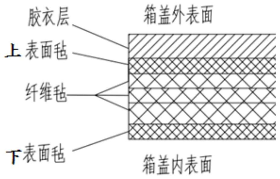
[0008] At present, the most widely used glass fiber reinforced plastic box cover, such as figure 1 As shown, the existing FRP box cover includes a gel coat layer, an upper surface felt, a fiber felt and a lower surface felt. There are still two important problems to be solved. One is the long-term high temperature resistance. After the temperature exceeds 500°C, it will be completely carbonized and become brittle. The thermal diffusion of the power battery can reach this temperature. Although there is no problem with the protection time of 5 minutes, there is a strong uncertainty if it is longer. At present, it is more than 8 minutes. There is a possibility of cracking and air rushing into the box, further promoting the occurrence of thermal expansion

Method used


Image

  • Power battery system composite material box cover and manufacturing method thereof
  • Power battery system composite material box cover and manufacturing method thereof
  • Power battery system composite material box cover and manufacturing method thereof

Examples


Embodiment Construction

[0035] Embodiments of the present invention are described in detail below, examples of which are shown in the drawings, wherein the same or similar symbols designate the same or similar elements or elements having the same or similar functions throughout. The embodiments described below by referring to the figures are exemplary only for explaining the present invention and should not be understood as limiting the present invention.

[0036] It is to be understood that the terms "center", "longitudinal", "transverse", "length", "width", "thickness", "upper", "lower", "front", "rear", "left", "Right", "Vertical", "Horizontal", "Top", "Bottom", "Inner", "Outer", "Clockwise", "Counterclockwise", "Axial", "Radial", "Circumferential" The orientation or positional relationship indicated to ", etc. is based on the orientation or positional relationship shown in the drawings, which is only for the convenience of describing the present invention and simplifying the description, rather t...


PUM

PropertyMeasurementUnit
densityaaaaaaaaaa
densityaaaaaaaaaa
thicknessaaaaaaaaaa

Abstract

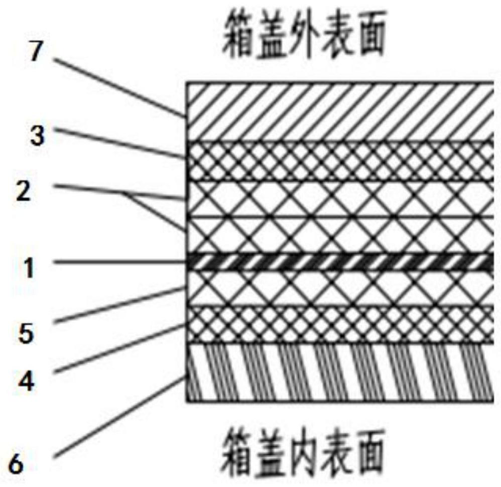
The invention discloses a power battery system composite material box cover and a manufacturing method thereof, the box cover comprises an electromagnetic shielding layer, an upper fiber felt layer, an upper surface felt layer, a lower surface felt layer and a lower fiber felt layer, and the upper surface felt layer, the upper fiber felt layer, the electromagnetic shielding layer, the lower fiber felt layer and the lower surface felt layer are sequentially laid from top to bottom. According to the invention, under the condition that the same thickness, weight, strength, price and other factors are guaranteed, due to the fact that the box cover is provided with the electromagnetic shielding layer, the Faraday cage effect is naturally formed after the box cover is combined with the box body (because the box body needs to be borne, the current box body is a metal piece); the EMC capacity of the whole battery system is further improved, even if the anti-electromagnetic interference of the BMS fails, the whole system can still meet the requirement for normal operation, meanwhile, the fireproof capacity of the box cover can be further improved by adding the fireproof layer, and the increasingly harsh heat expansion protection requirement is met.

Description

technical field [0001] The invention relates to the technical field of power battery installation equipment, in particular to a composite material case cover for a power battery system and a manufacturing method thereof. Background technique [0002] With the release of three mandatory national standards GB 18384-2020 "Safety Requirements for Electric Vehicles", GB 38032-2020 "Safety Requirements for Electric Buses" and GB 38031-2020 "Safety Requirements for Traction Batteries for Electric Vehicles", the country's requirements for power battery systems The safety requirements are getting higher and higher. Among them, it is required to have an alarm signal after the occurrence of thermal runaway, and to give the passengers 5 minutes to escape. The equivalent requirement of the OEM is that the entire battery system will The shell (including all appearance parts such as the box cover) is not broken, no obvious flames can be seen, and the time is often extended, changing from 5...

Claims


Application Information

Patent Timeline
Patent Type & Authority Applications(China)
IPC IPC(8): H01M50/282H01M50/24H01M50/249H05K9/00
CPCH01M50/282H01M50/24H01M50/249H05K9/0081Y02E60/10
Inventor 戴强项超龚亚飞
Owner 合肥墨郎科技有限公司
Learn More