Conveying trolley for concrete pre-embedded angle steel guide rails and use method of conveying trolley
A technology for transporting material trolleys and concrete, which is applied in the direction of transportation and packaging, cleaning devices, conveyor objects, etc., and can solve problems such as construction hazards, unstable lifting of steel structures, and dangerous handling and movement, and achieve the effect of convenient construction
- Summary
- Abstract
- Description
- Claims
- Application Information
AI Technical Summary
Problems solved by technology
Method used
Image

Examples
Embodiment Construction
[0031] The following will clearly and completely describe the technical solutions in the embodiments of the present invention with reference to the accompanying drawings in the embodiments of the present invention. Obviously, the described embodiments are only some, not all, embodiments of the present invention. Based on the embodiments of the present invention, all other embodiments obtained by persons of ordinary skill in the art without making creative efforts belong to the protection scope of the present invention.
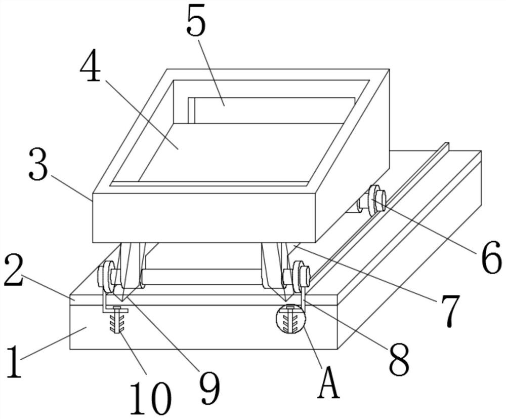
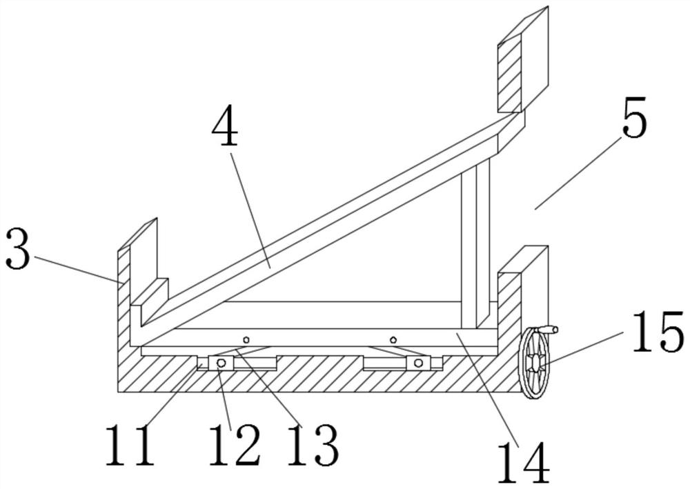
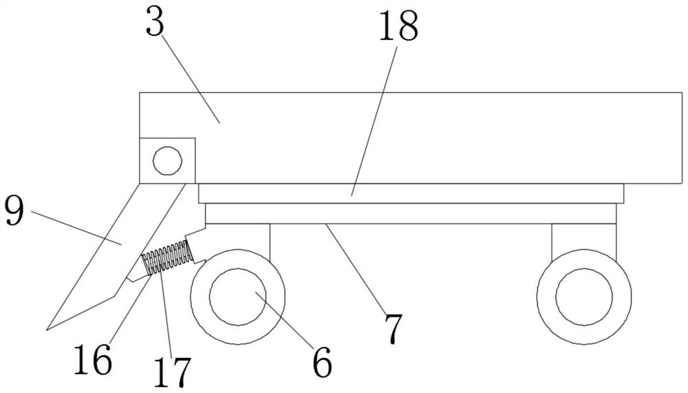
[0032] see Figure 1 to Figure 6 , the present invention provides a technical solution: a material transport trolley for pre-embedded angle steel guide rails in concrete, comprising a concrete layer 1 and a structural layer 2 arranged on the concrete layer 1, the inside of the concrete layer 1 is pre-embedded with an angle steel track 8, and the angle steel The lower end of the track 8 is provided with a reinforced anchor 10, the upper side of the angle steel ...
PUM
 Abstract
Description
Claims
Application Information