
Furnace top expansion device

An expansion device and expansion plate technology, applied in the direction of incinerators, combustion methods, combustion types, etc., can solve problems such as cracking of the top outer guard plate, achieve good overall shape, release deformation, and reduce unfavorable factors

Pending Publication Date: 2022-01-04
JIANGSU TAIHU BOILER
View PDF0 Cites 0 Cited by
  • Summary
  • Abstract
  • Description
  • Claims
  • Application Information

AI Technical Summary

Problems solved by technology

[0004] Today's garbage incinerators are equipped with multi-stage heating surfaces behind the furnace. The two-stage evaporator and the four-stage superheater are suspended and arranged in sequence along the front and rear of the boiler. The high-temperature flue gas will expand between each two-stage heating surfaces. If you continue to use The previous conventional outer guard plate will crack the top outer guard plate due to thermal expansion during the operation of the boiler

Method used


Image

  • Furnace top expansion device
  • Furnace top expansion device

Examples


Embodiment Construction

[0026] The specific embodiments of the present invention will be further described below in conjunction with the accompanying drawings.

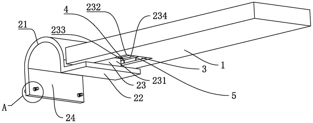
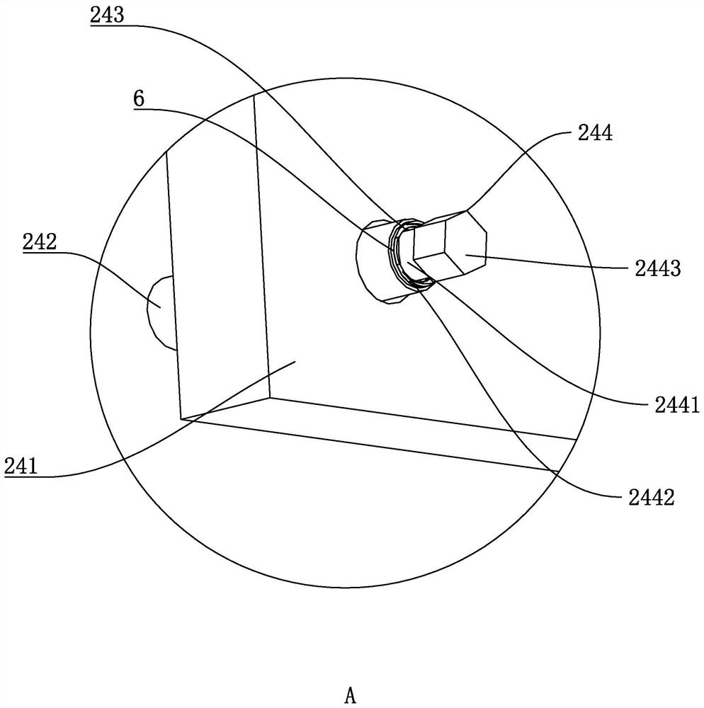
[0027] The technical scheme adopted in the present invention is: a furnace top expansion device, such as figure 1 and figure 2 As shown, it includes a rectangular straight plate 1, and the rectangular straight plate 1 is also provided with an anti-expansion device 2. The anti-expansion device 2 includes flexible expansion plates 21 located on both sides of the rectangular straight plate 1, and a connecting plate 22 is provided at the bottom of the flexible expansion plate 21, and The connecting plate 22 is provided with a connecting device 23 between the rectangular straight plate 1, and the flexible expansion plate 21 is bent and presents an inverted U shape. One end of the bottom of the flexible expanding plate 21 is welded to the connecting device 23, and the other end is also A fixing device 24 is provided, and the connecting device 23...


PUM


Abstract

The invention discloses a furnace top expansion device, and aims to provide a furnace top expansion device capable of effectively reducing fracture caused by high-temperature expansion. According to the technical scheme, the furnace top expansion device comprises a rectangular straight plate, wherein anti-expansion devices are arranged on the two sides of the rectangular straight plate, the anti-expansion devices comprise flexible expansion plates located on the two sides of the rectangular straight plate, connecting plates located at the bottoms of the flexible expansion plates and connecting devices located between the connecting plates and the rectangular straight plate, each flexible expansion plate is bent, one end of the bottom of each flexible expansion plate is welded to the connecting devices, and fixing devices are arranged at the other ends of the bottoms of the flexible expansion plates.

Description

technical field [0001] The invention relates to the field of boiler equipment, in particular to a furnace top expansion device. Background technique [0002] The garbage incinerator is a device for incinerating garbage. The garbage burns in the furnace and becomes waste gas, which enters the secondary combustion chamber, burns completely under the forced combustion of the burner, and then enters the spray dust collector. After dust removal, it is discharged into the atmosphere through the chimney . The garbage incinerator is composed of four major systems: garbage pretreatment system, incineration system, smog biochemical dust removal system and gas generator (auxiliary ignition and incineration). One. [0003] Garbage incinerator is a kind of harmless treatment equipment commonly used in the harmless treatment of medical and domestic waste and animals. Its principle is to use coal, fuel oil, gas and other fuels to burn and carbonize the objects to be treated at high temp...

Claims


Application Information

Patent Timeline
Patent Type & Authority Applications(China)
IPC IPC(8): F23G5/44F23G5/50
CPCF23G5/44F23G5/50
Inventor 管亿孙建涛杨琴王新
Owner JIANGSU TAIHU BOILER
Learn More