Line and tower footing automatic lofting method and system

A tower base and line technology, which is applied in the field of automatic stakeout methods and systems for lines and tower bases, can solve the problems of low calculation efficiency, inability to use different stakeout methods at the same time, cumbersome steps for data input and line construction, etc., and achieves good operation stability, The effect of improving the lofting efficiency of tower base and avoiding manual calculation and manual line construction errors

Pending Publication Date: 2022-01-04
SHANDONG ELECTRIC POWER ENG CONSULTING INST CORP
View PDF0 Cites 0 Cited by
  • Summary
  • Abstract
  • Description
  • Claims
  • Application Information

AI Technical Summary

Problems solved by technology

This method can stake out any straight tower and corner tower according to the designed semi-heel, but when the tower position is adjusted, the coordinates of the straight line direction point of the tower base need to be recalculated on site, and the error tolerance rate is low and the efficiency is low
[0006] In addition, the above two methods need to enter the corner coordinates in the total station or GPS handbook in the actual operation of tower foundation stakeout, and perform manual line building operations, the steps are cumbersome, and it is easy to cause misoperation
Moreover, line stakeout and tower base stakeout sometimes need to switch between two methods to complete, which is less efficient
[0007] That is to say, there are currently technical problems such as cumbersome steps for data input and line construction during the stakeout process of transmission lines and tower foundations, low efficiency in manual calculation of angles, distances, and coordinates, and inability to use different stakeout methods at the same time

Method used


Image

  • Line and tower footing automatic lofting method and system
  • Line and tower footing automatic lofting method and system
  • Line and tower footing automatic lofting method and system

Examples


Embodiment 1

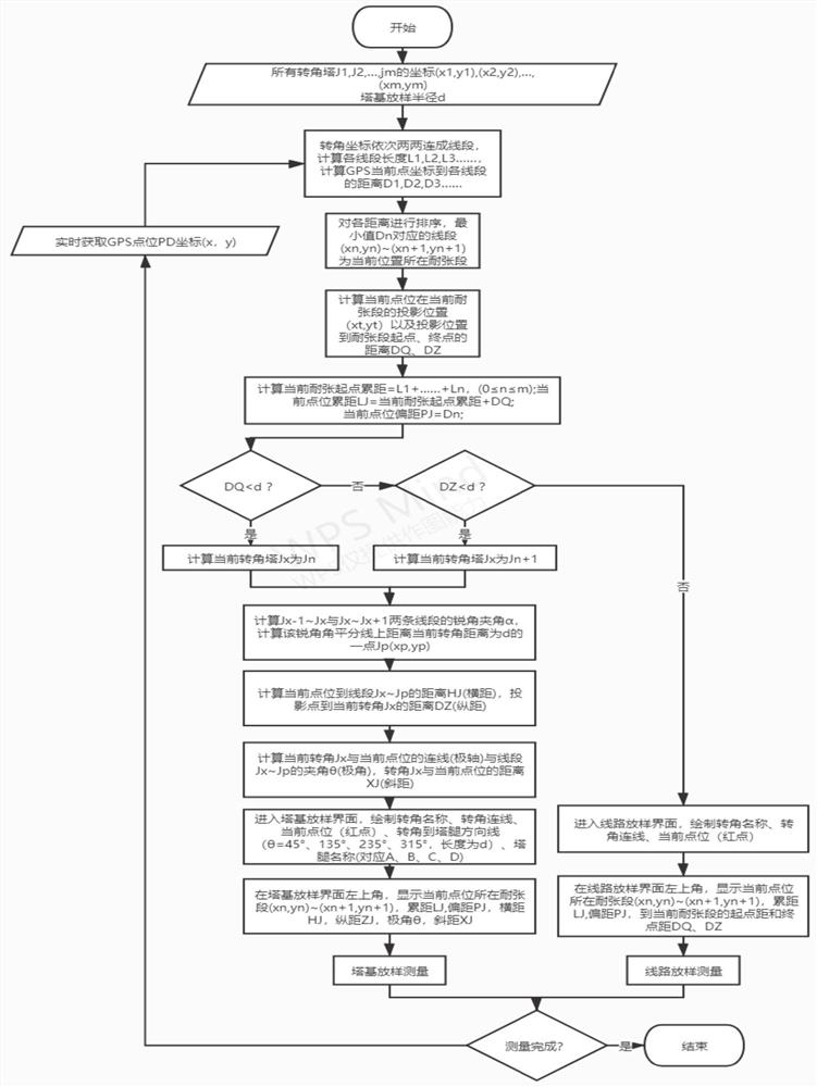
[0037] Such as figure 1 As shown, an automatic stakeout method for lines and tower bases, including:

[0038] Obtain the coordinates of the corner tower, the lofting radius of the tower base and the coordinates of the current point;

[0039] Input the coordinates of the corner tower, the tower base stakeout radius and the coordinates of the current point into the automatic stakeout model to obtain the stakeout measurement data, and carry out line and tower base stakeout according to the stakeout measurement data;

[0040] The automatic stakeout model obtains the tension section where the current point is located according to the input corner tower coordinates and the coordinates of the current point, and obtains the starting distance and the end point distance from the current point to the tension section; obtains according to the starting point distance and the end point distance The cumulative distance and offset distance of the current point in the entire line; if the star...

Embodiment approach

[0043] As an implementation, the acquisition of the corner tower coordinates, tower base stakeout radius and the coordinates of the current point can be positioned using GPS.

specific Embodiment approach

[0044] As a specific implementation, obtain the tension section of the current point according to the input corner tower coordinates and the coordinates of the current point, and obtain the starting point distance and the end point distance from the current point to the tension section. Steps include:

[0045] Connect the coordinates of the corner towers into line segments, obtain the length of each line segment, and obtain the distance from the current point coordinates to each line segment;

[0046] Sort the distances, and the line segment corresponding to the minimum value of the distance is the tension segment where the current point is located;

[0047] Obtain the projected position from the current point to the tension section and the starting and ending distances from the projected position to the tension end, and then obtain the accumulated distance from the beginning of the tension section, the accumulated distance from the current point and the offset from the current...


PUM


Abstract

The invention provides a line and tower footing automatic lofting method and system. The line and tower footing automatic lofting method comprises steps that coordinates of an angle tower, a lofting radius of a tower footing and coordinates of a current point location are obtained; the coordinates of the angle tower, the lofting radius of the tower footing and the coordinates of the current point location are inputted into an automatic lofting model to obtain lofting measurement data, and line and tower footing lofting is carried out according to the lofting measurement data; the automatic lofting model obtains the starting point distance and the ending point distance from the current point position to the strain section; an accumulated distance and an offset distance of the current point location in the whole line are obtained according to the starting point distance and the ending point distance; a tower position center coordinate of a starting point or an end point (depending on which distance between the starting point or the end point is smaller than a tower footing lofting radius) of a strain section is used as a lofting point, the lofting point is used as an original point of a rectangular coordinate system or a polar coordinate system, and an angular bisector of an acute angle included angle of two line segments which are adjacently connected with the lofting point is used as a y axis or a polar axis; the transverse distance, the longitudinal distance, the polar angle and the slant distance of the current point position relative to the lofting point are obtained, lofting measurement data are outputted, manual calculation and manual line building errors are avoided, and through field tests, tower footing lofting efficiency is improved by 80% under the condition that the precision of the lofting point is not changed, and operation stability is good.

Description

technical field [0001] The disclosure belongs to the technical field of power transmission engineering design, and in particular relates to an automatic lofting method and system for lines and tower foundations. Background technique [0002] The statements in this section merely provide background information related to the present disclosure and may not necessarily constitute prior art. [0003] At present, the stakeout methods for transmission lines and tower foundations are mainly polar coordinate method and line coordinate method. [0004] The polar coordinate method is the main method for setting out tower bases of total stations and theodolites, and this method is generally used when GPS is used for tower base setting out. When lofting tower foundations, the center coordinates of the rear, middle, and front three tower positions or the coordinates of the middle and rear two towers + the azimuth of the forward direction are known. Angle and distance, and then use the ...

Claims


Application Information

Patent Timeline
IPC IPC(8): G01C15/00
CPCG01C15/00Y02E10/72
Inventor 马超常增亮李斌高兴国徐永涵曲萌
Owner SHANDONG ELECTRIC POWER ENG CONSULTING INST CORP
Why Eureka
Try Eureka