Computer tomography imaging device and method

a computer tomography and imaging device technology, applied in the field of computer tomography imaging devices, can solve the problems of affecting the speed and accuracy of ct image, the hardware cost of the ct device, and the difficulty of large-scale imaging with high accuracy and medical imaging with low dose, so as to achieve convenient implementation and reduce radiation dose

Active Publication Date: 2016-07-05
TSINGHUA UNIV +1
View PDF17 Cites 149 Cited by
  • Summary
  • Abstract
  • Description
  • Claims
  • Application Information

AI Technical Summary

Benefits of technology

[0031]According to the X-ray CT imaging device and method in the present invention, the 2D / 3D slice image of a region of interest can be exactly reconstructed as long as the X-ray beam emitted from the X-ray source covers the region of interest, so it is possible to use a small-sized detector to perform CT imaging on the region of interest at any position of a large-sized object, which improves the speed of CT scanning and image reconstruction and cuts the hardware cost of a CT device, and meanwhile reduces to a great extent the radiation dose of the X-ray during the CT scanning. Therefore, the present invention is highly potential for market applications.

Problems solved by technology

Although CT technology has currently achieved great success in the fields of industry, security check, medical care and so on, due to the complexity and the diversity of engineering application conditions, high requirements are put forth for further development of CT technology.
In particular, in the industrial application, CT technology faces with many difficulties in terms of large-sized imaging with high accuracy and medical imaging with low dose, etc.
This is mainly because: the CT scanning field of view (FOV) is restricted by the width of the X-ray beam, the size of the detector and the angle of the view, which gives rise to the possibility that the projection data of the scanning of a large object has truncations in the two directions of the detector and the scanning angle; the current mainstream CT algorithms are all overall reconstruction methods with respect to an intact object, which require the X-ray beam to cover the slices of the object completely and can hardly deal with the occasion where the projection data is truncated.
Therefore, when imaging a large object or an irregular object, it is often difficult to perform the scanning directly, but instead, the ultimate image can only be reconstructed with approximate conversion methods such as data rearrangement after many times of scanning, which affects the speed and the accuracy of CT image adversely.
In addition, the detector of a CT device has been the key factor that influences the hardware cost of the CT device, and the price of the detector is directly proportional to the size and amount of the detector units.
However, the price of detector remains high, which greatly limits the cost margin of CT products.
On the other hand, in medical CT imaging, in order to ensure that the projection data of the X-ray is not truncated, the width of the X-ray beam for use in the current CT scanning must cover the width of the slices of the human body, however, the real interest region often only relates to a certain organ of the human body, and as a result, an unnecessary radiation dose on the human body during the CT scanning is greatly increased.
In this regard, currently mainstream whole body spiral CT machine cannot meet the requirements for a normal medical diagnosis.
However, due to the huge amount of data from the flat-panel detector, the data transmission speed still cannot meet the requirements for cone-beam CT imaging, and there are no CT devices using flat-panel detectors for whole body imaging in the practice.
However, as these functions could not replace the real slice image of the object, they could hardly meet the requirements for real engineering applications, which greatly impaired the significance of local CT imaging in real engineering applications.
Consequently, the study of local ROI imaging of an object had stagnated for a long term and could not find way out.
However, in real CT engineering applications, it is difficult to acquire information about the reconstruction values in the PI line inside the object in advance, so the method of Wang et al. has certain limitations in real applications.

Method used


Image

  • Computer tomography imaging device and method
  • Computer tomography imaging device and method
  • Computer tomography imaging device and method

Examples


Embodiment Construction

[0040]Further descriptions of the present invention are given as follows in combination with the figures and the specific embodiments.

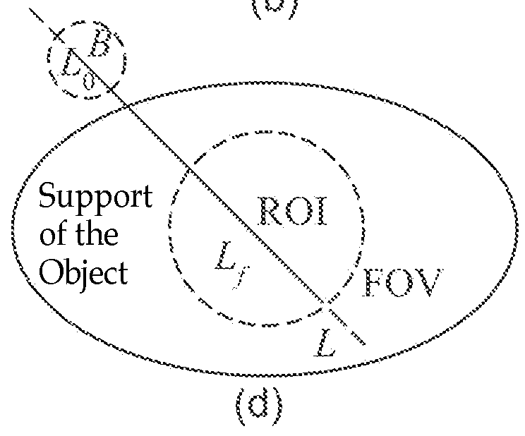
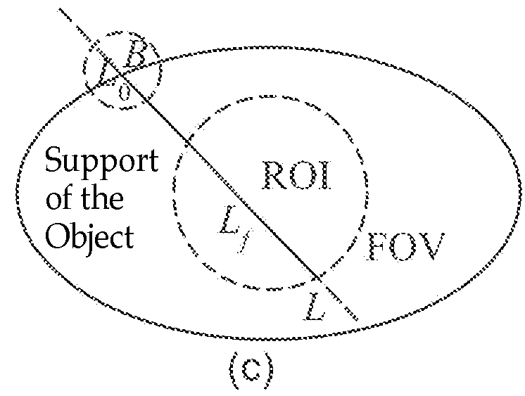
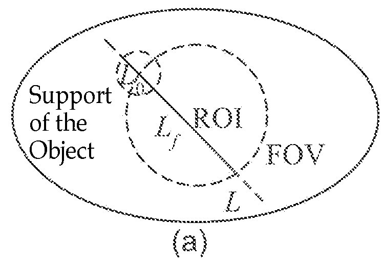
[0041]As mentioned above in the situation (d) about a sufficiency condition of exact CT data reconstruction, to exactly reconstruct the slice image of ROI, it only requires the acquisition of the X-ray projections passing through the ROI and the region B by means of scanning

[0042]FIG. 2 describes a computed tomography (CT) imaging method according to an embodiment of the present invention. In step S201, a region of interest (ROI) of an object under examination to be the CT imaging is determined, and a region B having at least a part falling outside the support of the object is determined based on the determined ROI. The region B is selected to enable a selection of a group of PI line segments covering the ROI, wherein each PI line passing through the ROI passes through the region B (as shown in FIG. 1 (d)). The region B can be a spatial region of any ...


PUM


Abstract

The present invention discloses a method for performing CT imaging on a region of interest of an object under examination, comprising: acquiring the CT projection data of the region of interest; acquiring the CT projection data of region B; selecting a group of PI line segments covering the region of interest, and calculating the reconstruction image value for each PI line segment in the group; and combining the reconstruction image values in all the PI line segments to obtain the image of the region of interest. The present invention further discloses a CT imaging device using this method and a data processor therein. Since the 2D / 3D slice image of the region of interest can be exactly reconstructed and obtained as long as the X-ray beam covers the region of interest and the region B, it is possible to use a small-sized detector to perform CT imaging on the region of interest at any position of a large-sized object, which reduces to a great extent the radiation dose of the X-ray during the CT scanning.

Description

CROSS-REFERENCE TO RELATED APPLICATIONS[0001]This is the U.S. national phase of International Application No. PCT / CN2009 / 001593, filed Dec. 30, 2009, which claims the benefit of Chinese Patent Application No. 200910085612.4, filed May 26, 2009.TECHNICAL FIELD[0002]The present invention relates to a computer tomography (CT) imaging device, in particular to a device for CT imaging of a region of interest (ROI), and a CT imaging method for use in the such devices as well as a computer program product and a recording medium for implementing the imaging method.BACKGROUND ART[0003]CT technology has brought revolutionary impact on medical diagnosis and industrial nondestructive testing even since Hounsfield has invented the first CT machine in 1972, and CT has been one of the important detection measures in the industries of medical treatment, biology, aeronautics and astronautics, national defense, etc. X-ray cone-beam CT has been widely used in the fields of clinical medicine, security c...

Claims


Application Information

Patent Timeline
Patent Type & Authority Patents(United States)
IPC IPC(8): G06T11/00A61B6/06A61B6/00A61B6/03
CPCA61B6/032A61B6/06A61B6/4452A61B6/469G06T11/006G06T2211/416G06T2211/421G06T2211/424
Inventor LI, LIANGCHEN, ZHIQIANGZHANG, LIKANG, KEJUNLI, YUANJINGLIU, YINONGXING, YUXIANGZHAO, ZIRAN
Owner TSINGHUA UNIV
Why Eureka
Try Eureka