Low-temperature drift phase range finder

A technology of phase ranging and low temperature drift, which is applied in the direction of measuring distance, instruments, measuring devices, etc., can solve problems such as large temperature drift, and achieve the effect of improving accuracy, reducing measurement errors, and eliminating errors.

Pending Publication Date: 2022-01-04
杭州隆硕科技有限公司
View PDF0 Cites 0 Cited by
  • Summary
  • Abstract
  • Description
  • Claims
  • Application Information

AI Technical Summary

Problems solved by technology

The program has a large temperature drift

Method used


Image

  • Low-temperature drift phase range finder
  • Low-temperature drift phase range finder

Examples


Embodiment Construction

[0034] The following will clearly and completely describe the technical solutions in the embodiments of the present invention with reference to the accompanying drawings in the embodiments of the present invention. Obviously, the described embodiments are only some, not all, embodiments of the present invention.

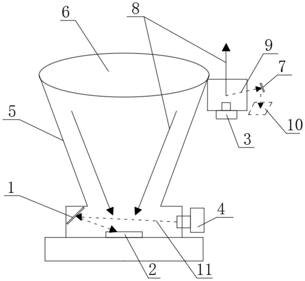
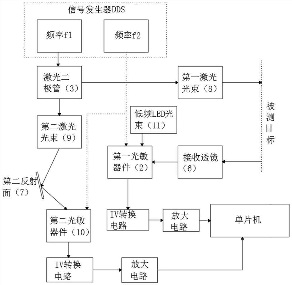
[0035] refer to Figure 1-2 , a low-temperature drift phase range finder, comprising: an optical machine body 5, a laser diode 3, a first photosensitive device 2, and a second photosensitive device 10; the laser diode 3 emits a laser beam a8 to the surface of the measured target, and the laser beam a8 passes through After the target is reflected, it is irradiated on the receiving lens 6 in the optical machine body 5 and is received by the first photosensitive device 2 through the receiving lens 6; the laser diode 3 emits the laser beam b9 to the second reflecting surface 7, and the laser beam b9 passes through the second reflective surface 7. The reflective surface 7...


PUM


Abstract

The invention discloses a low-temperature drift phase range finder which comprises an optical machine body, a laser diode, a first photosensitive device and a second photosensitive device, wherein the laser diode emits a laser beam a to the surface of a measured target, and the laser beam a is reflected by the measured target, then irradiates a receiving lens in the optical machine body and is received by the first photosensitive device through the receiving lens; and the laser diode emits a laser beam b to a second reflecting surface, and the laser beam b is reflected by the second reflecting surface and then is received by the second photosensitive device. In the low-temperature drift phase range finder, the light beam emitted by the laser diode is reflected by the object to irradiate the first photosensitive device to obtain a phase Ta, a part of the same light beam emitted by the same laser diode is reflected by the optical machine to irradiate the second photosensitive device to obtain a phase Tb, and the Ta and the Tb are subtracted to eliminate the temperature drift of the laser diode, thus errors caused by temperature changes are eliminated.

Description

technical field [0001] The invention relates to the field of board technology, in particular to a low-temperature drift phase range finder. Background technique [0002] As is known, the phase laser rangefinder measures the phase delay generated by the round-trip distance of continuous modulated light waves, and indirectly measures the flight time between the light in the air and the target to be measured, thereby calculating the measured distance. It is as follows: the high-frequency signal f1 is modulated on the semiconductor laser tube, so that the laser tube produces continuous high-frequency light and dark laser light, and the high-frequency signal f2 is modulated on the photodiode. After the photodiode is mixed and filtered, the low-frequency signal f1-f2 is obtained, and the measured distance is calculated by calculating the phase of the low-frequency signal (f1-f2). The laser diode has a certain phase delay for the signal modulated on it, and the phase delay of diffe...

Claims


Application Information

Patent Timeline
Patent Type & Authority Applications(China)
IPC IPC(8): G01S17/48
CPCG01S17/48
Inventor 龚志
Owner 杭州隆硕科技有限公司
Why Eureka
Try Eureka