Double-optocoupler image direct voltage sensor

A DC voltage and sensor technology, which is applied in the direction of measuring current/voltage, instruments, and measuring electrical variables, etc., can solve the problems of inability to detect voltage sensing circuits, large voltage sensors, and cannot be designed and applied, so as to eliminate the phenomenon of temperature drift , light weight and simple structure

Active Publication Date: 2017-10-03
HENAN INST OF SCI & TECH
View PDF5 Cites 0 Cited by
  • Summary
  • Abstract
  • Description
  • Claims
  • Application Information

AI Technical Summary

Problems solved by technology

Since there is no reference comparison under the same conditions, the feedback voltage has fluctuations and cannot be used as a voltage sensing and detection circuit for the measurement system
[0004] Voltage sensors or transmitters mostly use electromagnetic conversion transmission technology, which is large in size, low in accuracy, and low in the measurement voltage range; voltage sensors using functional optical fiber technology are expensive and also have temperature effects
The above voltage sensor is bulky and cannot be directly designed and applied to the low-voltage control system as a device

Method used


Image

  • Double-optocoupler image direct voltage sensor
  • Double-optocoupler image direct voltage sensor
  • Double-optocoupler image direct voltage sensor

Examples


Embodiment 1

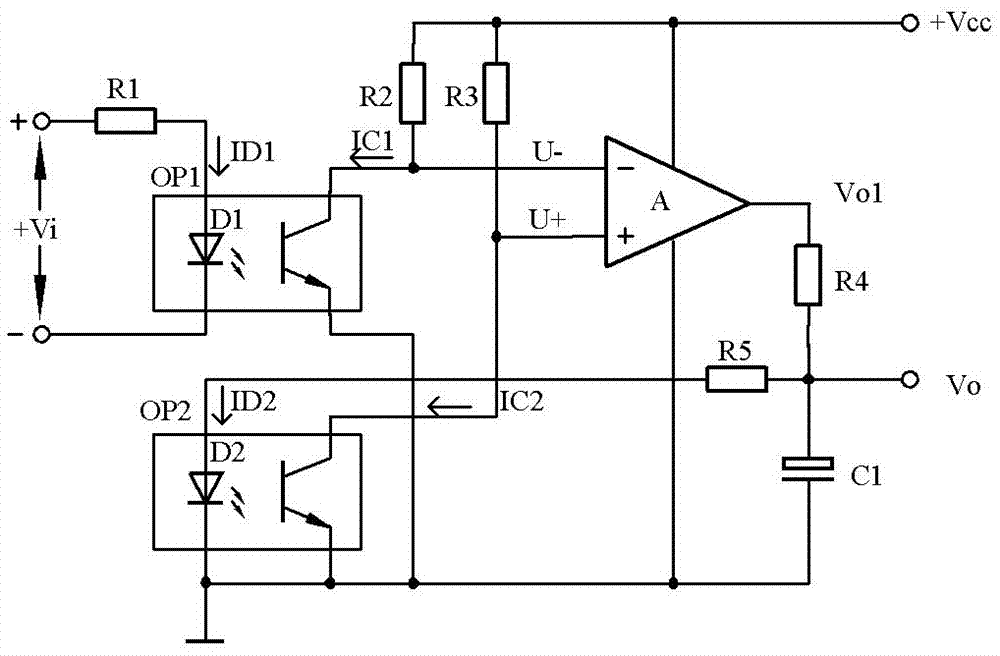
[0020] see figure 1 , the dual optocoupler mirror image DC voltage sensor of the present invention comprises a detected high voltage signal input end, a mirror image current control circuit and a detection signal output end, and the mirror image current control circuit consists of two optocouplers (optocoupler OP1, optocoupler OP1, OP2 forms double optocoupler), voltage comparator A, low-pass filter form; In work, described mirror current control circuit guarantees that the electric current of the output terminal of two optocouplers is equal; The input terminal of first optocoupler OP1 passes resistance R1 Connect the positive pole of the DC high-voltage power supply to be tested, and the output terminal is connected to the inverting input terminal of the voltage comparator through the pull-up resistor R2; the output terminal of the voltage comparator is connected to a low-pass filter circuit, and the output of the low-pass filter circuit is connected to the first The input te...

Embodiment 2

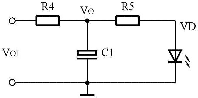
[0022] see figure 1 , the dual optocoupler mirror image DC voltage sensor of this embodiment differs from Embodiment 1 in that: the low-pass filter circuit is composed of resistors R4, R5 and capacitor C1, and the output terminal of the voltage comparator passes through resistor R4 and capacitor C1 Grounded, the node of the resistor R4 and the capacitor C1 is the detection signal output terminal, and the node of the resistor R4 and the capacitor C1 is connected to the power input terminal of the second optocoupler OP2 through the resistor R5 at the same time.

Embodiment 3

[0024] Such as figure 1 As shown, in the dual optocoupler mirror image DC voltage sensor of this embodiment, the optocouplers OP1 and OP2 have the same parameters, R2=R3, and A is an operational amplifier, which is used for voltage comparison here. When there is Vi input, the current of Vi is limited by R1, the LED in the optocoupler OP1 gets the current ID1 to turn on, and the collector of the phototransistor in OP1 has the current IC1, IC1=kID1, where k is the optocoupler current conversion coefficient. U-=VCC-IC1*R1.

[0025] At this time, if U+ is greater than U-, VO1 increases and ID2 increases. After photoelectric conversion by the optocoupler, IC1 increases, causing U+ to decrease. When U+ is less than U-, VO1 decreases, which causes U+ to rise in the same way, and finally the circuit reaches Steady state, at this time U+=U-, ID1=ID2. but

[0026]

[0027] The optocoupler OP1 and OP2 have the same parameter VD1=VD2=VD, sorted out

[0028]

[0029] When the ID1...


PUM


Abstract

The invention relates to a voltage measurement sensor, in particular to a double-optocoupler image direct voltage sensor. The sensor comprises a detected high voltage signal input end, an image current control circuit and a detection signal output end, wherein the image current control circuit comprises two optocouplers with the same electrical parameter, a voltage comparator and a low-pass filter; an input end of the first optocoupler is connected with a to-be-detected direct current high-voltage power supply anode; an output end of the first optocoupler is connected with an inverted input end of the voltage comparator via a pull-up resistor R2; an output end of the voltage comparator is connected with a low-pass filter circuit; an output of the low-pass filter circuit is connected with an input end of the second optocoupler; an output of the second optocoupler is connected with a non-inverted input end of the voltage comparator via a pull-up resistor R3; the low-pass filter circuit extracts an output signal of the voltage sensor; the resistance of the resistors R2 and R3 is equal. According to the sensor, voltage detection of a high-voltage power supply end of equipment by a low-voltage system in the electrical equipment is achieved, the temperature drift is small, the precision is high, and the high-voltage end is completely isolated from the low-voltage system.

Description

technical field [0001] The invention relates to a DC voltage sensor, in particular to a voltage detection sensor which utilizes a low-voltage system to realize accurate measurement of high-voltage power supply voltage. Background technique [0002] The voltage detection system works in the low-voltage power supply system. In order to detect, remotely monitor and control the high-voltage power supply of electrical equipment, transformers, transformers or magnetic effect sensors are often used as high-voltage transmitters, sensors or voltage couplers. Limited by power and transformation ratio, traditional voltage sensors are bulky, have low voltage detection range, are easily affected by changes in temperature, magnetic circuit, and working environment, have defects such as low measurement accuracy, and temperature drift. Functional fiber optic voltage sensors are expensive, bulky, and have temperature drift, which cannot meet the high voltage detection requirements of the pow...

Claims


Application Information

Patent Timeline
Patent Type & Authority Applications(China)
IPC IPC(8): G01R19/00
CPCG01R19/0023
Inventor 白林锋赵明富王应军左现刚蔡磊
Owner HENAN INST OF SCI & TECH
Why Eureka
Try Eureka