Diaphragm and laser

A technology of lasers and apertures, applied in optics, instruments, optical components, etc., can solve problems such as the impact of optical system performance, affecting equipment performance, etc., to avoid half-wave loss, prevent energy concentration, and reduce the impact of service life. Effect

Pending Publication Date: 2022-01-04
深圳市先地图像科技有限公司
View PDF19 Cites 0 Cited by
  • Summary
  • Abstract
  • Description
  • Claims
  • Application Information

AI Technical Summary

Problems solved by technology

Therefore, dust falling on optical components such as lenses or light sources will have a greater impact on the performance of the optical system; this effect is particularly prominent in lithography direct writing equipment that requires high precision, even in laser welding or laser The accumulation of dust in the optical system of cutting equipment will also greatly affect the performance of the equipment

Method used


Image

  • Diaphragm and laser
  • Diaphragm and laser
  • Diaphragm and laser

Examples


Embodiment Construction

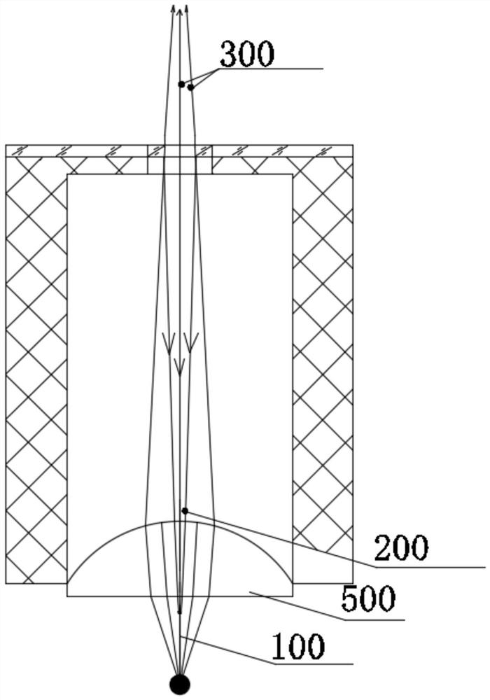
[0025] The "principal optical axis" in this application document refers to the straight line passing through the centers of the two spherical surfaces of the thin lens in geometric optics; Part of the beam; "aperture hole" should be understood as the optical space (shape) that constrains the light emitted from optical elements such as lenses or light sources to this "aperture hole" to obtain the beam we need for parts processing and other operations , it can be an unfilled through hole, or a light-transmitting hole filled with a transparent material. The shape of the hole can be a circle or other polygons, such as a hexagon. Other words, words, and sentences in this application document, unless otherwise specified, if they are professional terms in the field of optics, can be understood according to the meanings specified in the industry terms. Usually the meaning is understood.

[0026] In the prior art, since the diaphragm is often located at the end of the optical system, ...


PUM


Abstract

On the basis of any one embodiment, the embodiment of the invention further provides a laser which can comprise a light source circuit, a laser base and the diaphragm in any one embodiment. The diaphragm is installed on the laser base, the specific connection mode can be detachable connection or non-detachable connection, and the specific connection mode is not limited. A containing space for containing a light source circuit is arranged in the laser base in an extending mode, and the specific shape of the laser base can be reasonably arranged according to requirements and is not limited. A light source circuit of the laser is used for generating laser with a preset wavelength in a preset laser propagation direction. The specific implementation mode of the light source circuit is mature in the prior art, and is not described herein. According to the technical scheme, the embodiment is only used for explaining the technical scheme of the invention instead of limiting the technical scheme; although detailed description is carried out on the method by referring to the embodiment, ordinary technicians in the field should understand that the technical schemes recorded in the embodiments can still be modified or part of the technical characteristics can be equivalently replaced; the modification or replacement does not make the essence of the corresponding technical scheme break away from the spirit and range of the technical scheme of each embodiment of the invention.

Description

technical field [0001] Embodiments of the present invention provide an aperture and a laser, which relate to the field of optics, and in particular to optical elements in the field of optics. Background technique [0002] In the optical system, the diaphragm is often used to restrict the beam to obtain a better available beam, but during the use of the optical system, dust often falls through the diaphragm hole or end face hole of the diaphragm base to the optical components such as the lens or light source. superior. The dust falling on optical components such as lenses or light sources is difficult to be cleaned in time due to the structure of the optical system and other reasons. [0003] The essence of dust is tiny particles of various substances. When light shines on dust, phenomena such as emission, diffuse reflection, and refraction will occur. Therefore, dust falling on optical components such as lenses or light sources will have a greater impact on the performance...

Claims


Application Information

Patent Timeline
Patent Type & Authority Applications(China)
IPC IPC(8): G02B5/00G02B27/00
CPCG02B5/00G02B5/005G02B27/0081G02B27/0006
Inventor 陈乃奇陈钢张向非
Owner 深圳市先地图像科技有限公司
Why Eureka
Try Eureka