System and method for exposing material with images

An image-to-image technology, which is applied in the direction of microlithography exposure equipment, photolithography exposure device, pattern surface photographic process, etc., can solve the problems of reducing brightness uniformity difference, etc. effect of tolerance

Pending Publication Date: 2022-01-04
VISITECH AS
View PDF1 Cites 0 Cited by
  • Summary
  • Abstract
  • Description
  • Claims
  • Application Information

AI Technical Summary

Problems solved by technology

This document does not address the problem of reducing the influence of edge portions of adjacent exposed stripes on exposure results caused by differences in image position and / or differences in brightness uniformity on two adjacent exposed stripes

Method used


Image

  • System and method for exposing material with images
  • System and method for exposing material with images
  • System and method for exposing material with images

Examples


Embodiment Construction

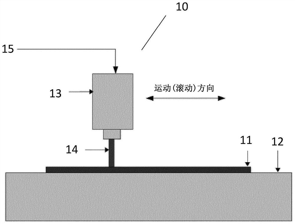
[0038] exist figure 1 In , a system 10 for exposing photosensitive or photopolymerizable material 11 layer by layer to build 3D objects or for 2D direct imaging lithography is shown.

[0039] The system includes an exposure table 12 and an electron light projector 13 arranged above the exposure table 12 . The electro-optical projector 13 may emit light 14 towards the exposure station 12, and thus onto any medium 11 arranged on the exposure station 12, thereby projecting an image onto the medium. For example, medium 11 is a photosensitive or photopolymerizable material. The electronic light projector 13 is moved relative to the exposure material 11 while a synchronization signal 15 is provided by the motor controller to enable the light projector to set the next image in the sequence of images.

[0040] This electronic light projector includes spatial modulators, such as DLP / LCD / LCOS or similar light / power projectors, used in 3D printers / rapid manufacturing machines or 2D lit...


PUM


Abstract

A system for exposing a material with images comprises an exposure table (12) and an electronic light projector (13) arranged above the exposure table (12) and adapted to project images towards a material arranged at the exposure table (12). The electronic light projector and the exposure table are configured to be moved relative each other, and the electronic light projector (13) is connected to a projector control unit. The projector control unit is configured to provide a sequence of images to be exposed represented by image data, superimpose a static image pattern onto the edge sections of the images to be exposed, thereby resulting in a sequence of combined images, and the electronic light projector (13) is configured to expose the combined images sequentially onto the material.

Description

technical field [0001] The present invention relates to a method that eliminates the Undesirable discontinuity effects in adjacent exposed stripes. Typical uses would be 3D printers, rapid prototyping machines, rapid manufacturing machines, and similar step-by-step lithography machines, in addition to 2D direct lithography machines for lithography related to the fabrication of PCBs, touch panels, solar cells, chemical milling, and others. layer construction craft equipment. Background technique [0002] When two adjacent exposed strips are placed close together, the polymerized material will depend on the position of the exposed strips and the power in each strip. The results will be optimal if the positions of the exposed stripes are well aligned relative to each other in the x and y directions (i.e. on the same grid as the image pixels), and if the power in the exposed stripes is the same. Adjacent exposed strips can then be placed close to each other ("back-to-back") o...

Claims


Application Information

Patent Timeline
Patent Type & Authority Applications(China)
IPC IPC(8): G03F7/20B29C64/124B33Y10/00
CPCG03F7/70416G03F7/70383G03F7/70475B33Y10/00G03F7/70558B33Y30/00B33Y50/02B29C64/129B29C64/393B29C64/286B29C64/268B29C64/10B29C64/20B29C64/386B33Y50/00G03F7/20G03F7/70B29C64/264B29C64/124B29C64/236G03F7/7055
Inventor 恩德雷·柯克霍恩特龙·约尔根森约翰·达埃
Owner VISITECH AS
Why Eureka
Try Eureka