An aircraft climate test connecting device and its parameter optimization method

A climate test and connecting device technology, which is applied in the direction of aircraft component testing, connecting components, measuring devices, etc., to achieve good heat preservation, ensure integrity, and reduce production costs

Active Publication Date: 2022-02-18
CHINA AIRPLANT STRENGTH RES INST
View PDF17 Cites 0 Cited by
  • Summary
  • Abstract
  • Description
  • Claims
  • Application Information

AI Technical Summary

Problems solved by technology

[0006] In order to achieve the above objectives, the present invention provides a connecting device for aircraft climate test and its parameter optimization method, which not only solves the problem of vertical connection between the thermal insulation wall panels and the floor around the climate test room, but also determines the The optimal parameters of the connection device ensure that the thermal insulation and sealing performance of the test environment during aircraft testing is close to the maximum theoretical value

Method used


Image

  • An aircraft climate test connecting device and its parameter optimization method
  • An aircraft climate test connecting device and its parameter optimization method
  • An aircraft climate test connecting device and its parameter optimization method

Examples


Embodiment 1

[0051] The main purpose of embodiment 1 is to set forth the structural design of the present invention under concrete parameters, and concrete technical scheme is as follows:

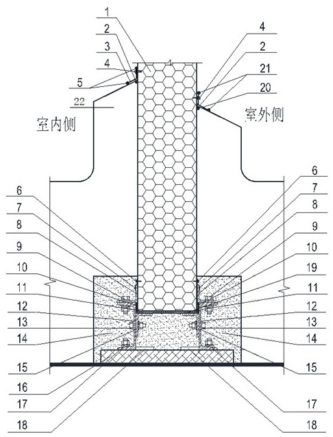
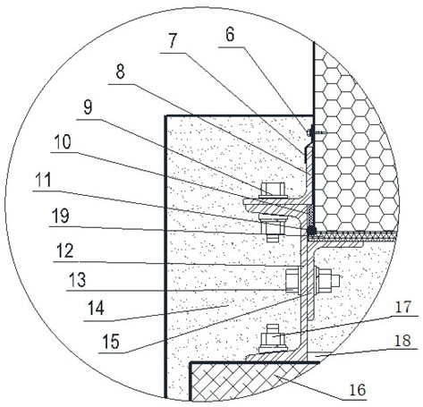
[0052] see figure 2 , 3 , an aircraft climate test connection device designed by the present invention, comprising a base arranged in the floor, and a thermal insulation wall plate 1 vertically inserted in the base;

[0053] Taking the section perpendicular to the plane where the thermal insulation wallboard 1 is located as the observation plane, the base includes anti-corrosion wood pads horizontally set on the floor surface -0.62m plane with length×width×thickness=450mm×240mm×50mm 16. A 16a hot-dip galvanized full-length channel steel 12 is respectively arranged on both sides of the top surface of the anticorrosive wood spacer 16 at a distance of 120mm from the edge; The lower side flange stands on the top surface of the anti-corrosion wood pad 16, and the anti-corrosion wood pad 16 is connected wi...

Embodiment 2

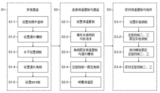
[0066] The narration basis of embodiment 2 is the scheme recorded in embodiment 1, aiming to illustrate the parameter optimization method of the connection device described under specific parameters, see figure 1 ,Specific steps are as follows:

[0067] S1. Install the base

[0068] S1-1. Taking the cross-section perpendicular to the plane where the thermal insulation wallboard 1 is located as the observation plane, horizontally set the anti-corrosion wood block 16 of length × width × thickness = 450mm × 240mm × 50mm on the floor surface -0.62m plane, The plane formed by the long thick sides of the anti-corrosion wood block 16 is parallel to the observation plane;

[0069] S1-2, a 16a hot-dip galvanized full-length channel steel 12 is respectively arranged at both sides of the top surface of the anti-corrosion wood pad 16 at 120 mm from the edge, and the anti-corrosion wood pad 16 is connected to each full-length channel steel 12 The adjacent flanges are all connected by bol...


PUM


Abstract

The present invention relates to the technical field of aircraft testing, in particular to an aircraft climate test connection device and a parameter optimization method thereof; the connection device vertically and rigidly connects a 200mm thick thermal insulation wall plate at a position of 0.62m on the floor surface at a distance of 300mm In the high base, the heat preservation, sealing and impact strength of the connection can be guaranteed to meet the requirements of the climate laboratory; the connection device designed by the invention fits the standard size heat preservation wallboard, and can be modularized together, which can greatly reduce the production cost. Cost, not only that, the parameter optimization method of the present invention can not only ensure that the thermal insulation and sealing performance of the test environment during the aircraft climate test is close to the maximum theoretical value, but also greatly shorten the construction period due to the standardized construction process.

Description

technical field [0001] The invention relates to the technical field of aircraft testing, in particular to an aircraft climate test connection device and a parameter optimization method thereof. Background technique [0002] The "aircraft test" recorded in the present invention refers to "climate environment adaptability test in the full-state aircraft laboratory", which refers to taking a full-state aircraft as the object, under the simulated climate environment conditions (including high temperature, low temperature) in the climate test room. , temperature-humidity, rain, fog, snowfall, freezing rain / icing and solar radiation and other typical climatic environments), according to the specified conditions and test sequences, let the aircraft withstand various climatic and environmental stresses, so as to obtain aircraft and Information on the limit capability of its ground support equipment to withstand the climate environment, and comprehensively evaluate its climate enviro...

Claims


Application Information

Patent Timeline
Patent Type & Authority Patents(China)
IPC IPC(8): G01M99/00B64F5/60F16B13/10
CPCG01M13/00B64F5/60F16B13/04
Inventor 曹琦陆国杰强宝平苏杭任红云
Owner CHINA AIRPLANT STRENGTH RES INST
Why Eureka
Try Eureka