
Sandblasting or spraying method for slit workpiece

A workpiece, sandblasting technology, applied in the direction of the spraying device, etc., can solve the problems of difficult removal of the iron sheet, hidden quality problems, etc., and achieve the effects of good quality, high efficiency, and convenient installation and disassembly

Active Publication Date: 2022-08-02
HUANENG GRP R&D CENT CO LTD +2
View PDF0 Cites 0 Cited by
  • Summary
  • Abstract
  • Description
  • Claims
  • Application Information

AI Technical Summary

Problems solved by technology

However, after the spraying is completed, there are still gaps in the iron sheet in the gap, and the sand particles impacted at high speed during the sandblasting process are stuck in the gap between the iron sheet and the workpiece, making it very difficult to remove the iron sheet after the work is completed, and there are certain quality risks.

Method used


Image

  • Sandblasting or spraying method for slit workpiece
  • Sandblasting or spraying method for slit workpiece
  • Sandblasting or spraying method for slit workpiece

Examples


Embodiment 1

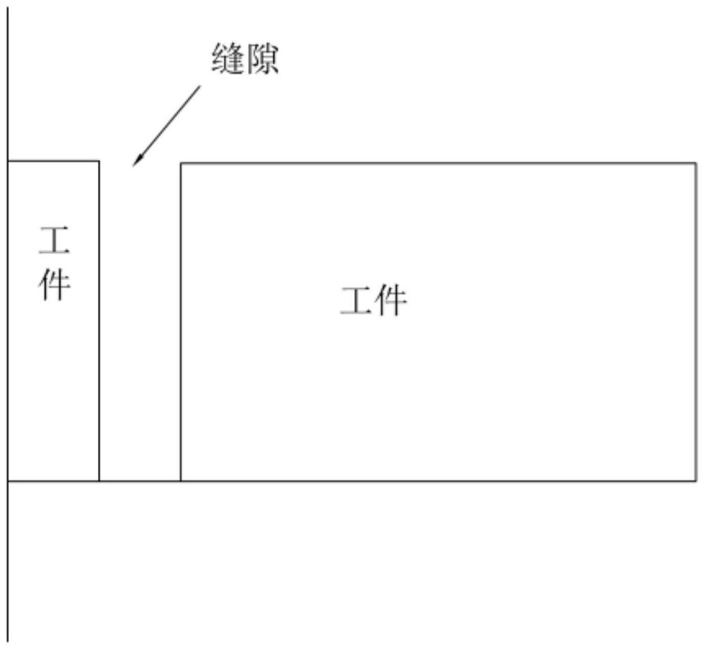
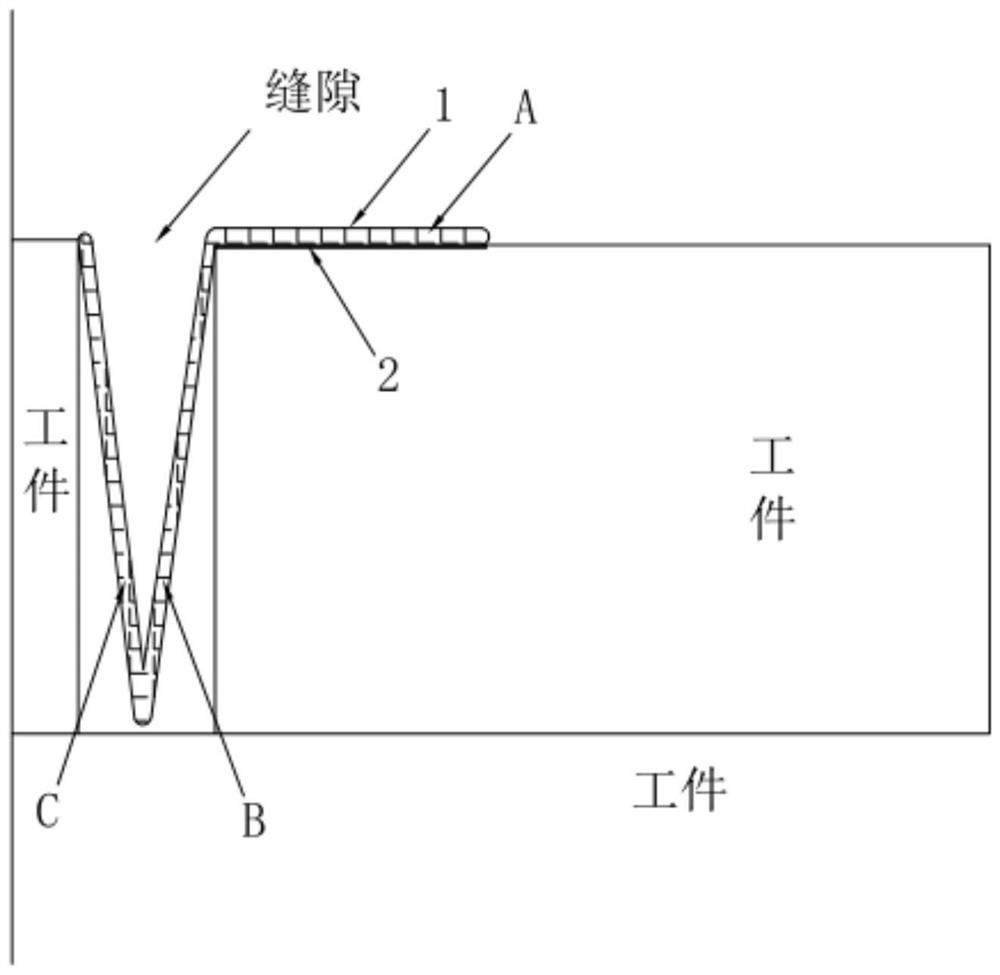
[0046] A sandblasting or spraying method for slit workpieces, combined with figure 1 and figure 2 shown, including the following steps:

[0047] Step S1, first measure the width of the gap with a caliper, the measurement result shows that the width of the gap at this position is 4 mm, select a shielding material, and the shielding material is a plastically deformable metal material, such as an iron sheet for the shielding material or an alloy sheet for the shielding material, and the shielding material is selected. The thickness of 0.4mm thickness iron sheet.

[0048] Step S2, forming the shielding material into a V-shape, one side of the shielding material is provided with part A of the cantilever 1, and the size of the opening of the V-shaped shielding material is equal to the width of the workpiece gap minus twice the thickness of the shielding material; It is required to be folded into a V-shape. The width of the V-shape opening is the slit width of 4mm minus twice the ...

Embodiment 2

[0055] The difference between this embodiment and the shielding method of Embodiment 1 is that the support structure is configured as a trapezoidal block. The material of the trapezoidal block can be metal, cork, rubber, plastic, etc. The trapezoidal block makes the iron sheet of the C part close to the surface of the workpiece.

Embodiment 3

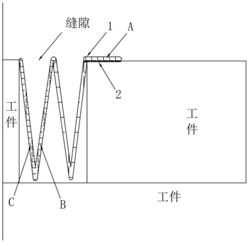
[0057] The difference between this embodiment and the shielding method of Embodiment 1 is that refer to image 3 , Design the masking material into a W shape.


PUM


Abstract

The invention relates to the technical field of machining of mechanical workpieces, and discloses a sandblasting or spraying method for slit workpieces, which solves the technical problems existing in the two methods of traditional high-temperature tape shielding and iron sheet shielding, and includes the following steps: Step S1, selecting shielding material; step S2, forming the shielding material into a V-shape; step S3, inserting the formed shielding material into the gap of the workpiece evenly; step S4, setting a support between the B part and the C part of the shielding material structure; step S5, start sandblasting or spraying operation; step S6, dismantle the support structure, and remove the shielding material to complete the sandblasting or spraying operation. According to the above technical solutions, the present invention designs a V-shaped shielding material with cantilever wings to shield the workpiece gap, and the V-shaped shielding material is easy to install and disassemble, and has good efficiency and high quality, so as to achieve spraying on the workpiece. For sand or spray process optimization purposes.

Description

technical field [0001] The invention relates to the technical field of machining of mechanical workpieces, and more particularly, to a sandblasting or spraying method for slit workpieces. Background technique [0002] Power system components are increasingly using thermal spray technology to protect their surfaces. In coal-fired power plants, hydropower plants, and gas-fired power plants, in order to improve the service life of equipment and prolong the maintenance cycle of units, thermal spraying technology is often used to protect the surfaces of components that are subject to corrosion, wear, water erosion, and cavitation. In the process of thermal spraying, the sandblasting link is particularly important. Due to the control of the spraying area, usually a component is sprayed only for the severely worn area, and the area that is not sprayed needs to be shielded to avoid contamination by the coating. In line with the size requirements, the masking of this area is particu...

Claims


Application Information

Patent Timeline
Patent Type & Authority Patents(China)
IPC IPC(8): B05B12/28
CPCB05B12/28
Inventor 周大鹏张璐刘刚江雄郎梼王铭辉袁东刘加将延帅黄子三
Owner HUANENG GRP R&D CENT CO LTD
Learn More