Multi-row drill automatic feeding and discharging device

An automatic loading and unloading and positioning device technology, which is applied in metal processing and other directions, can solve problems such as high labor intensity, and achieve the effect of solving high labor intensity

Pending Publication Date: 2022-01-11
山东光明园迪儿童家具科技有限公司
View PDF0 Cites 1 Cited by
  • Summary
  • Abstract
  • Description
  • Claims
  • Application Information

AI Technical Summary

Problems solved by technology

[0004] The object of the present invention is to provide an automatic loading and unloading device for multi-row drills to solve the problem of high labor intensity for workers in the production process.

Method used


Image

  • Multi-row drill automatic feeding and discharging device
  • Multi-row drill automatic feeding and discharging device
  • Multi-row drill automatic feeding and discharging device

Examples


Embodiment 1

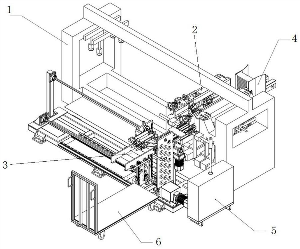
[0036] refer to Figure 2-5 , the sheet conveying assembly 4 spans above the bottom of the multi-row drill body 1, and consists of a left sheet conveying chain 41, a right sheet conveying chain 42 and a left sheet conveying chain 41, right The sheet material conveying chain 42 is composed of a polygonal shaft 43, and the width between the left sheet conveying chain 41 and the right sheet conveying chain 42 can be connected horizontally and telescopically, and the sheet material is conveyed longitudinally. The pressing plate assembly 2 is arranged above the sheet material conveying assembly 4 and is tightly connected with the multi-row drill body 1; Move the plate to the moving plate car 6.

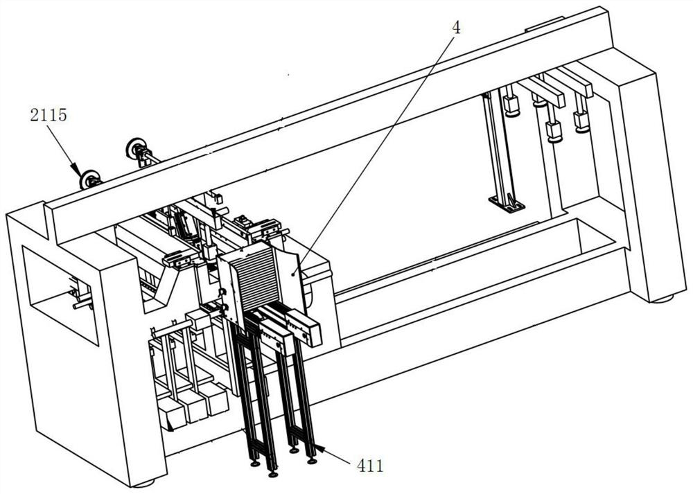
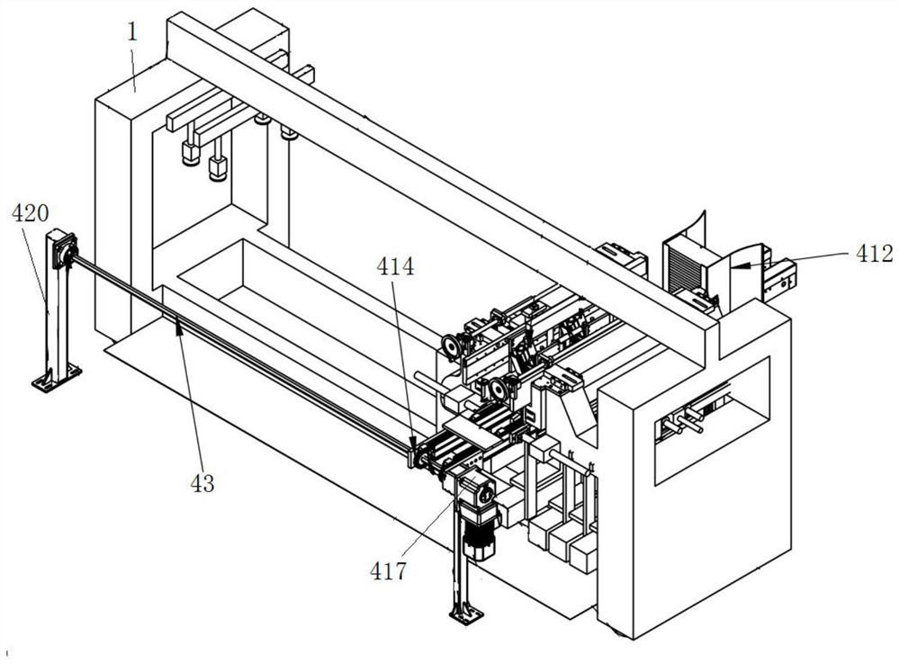
[0037] The left sheet material conveying chain 41 includes a support frame 411, a left storage plate box cover 412, a left chain groove plate 413, a chain 414, a left driven sprocket set 415, a left driving sprocket set 416, a drive motor 417 and a reversing Gear box, motor support feet ...

Embodiment 2

[0045] refer to Figure 6-7 , the platen assembly 2 includes two positioning devices 21 , the positioning devices 21 are installed on the frame of the multi-row drill body 1 , respectively corresponding to the upper side of the left sheet conveying chain 41 and the right sheet conveying chain 42 . It is used to press the sheets on the left sheet conveying chain 41 and the right sheet conveying chain 42 .

[0046] The positioning device 21 includes a device base plate 211, a drill body connecting plate 212 and a position adjustment mechanism; the position adjustment mechanism is connected with the device base plate 211, and the position adjustment mechanism is connected with a connecting plate 1 213 and a connecting plate 2 214; the first connecting plate 213 is installed on the There is a cylinder 1 215, a connecting plate 214 is installed with a cylinder 2 216; a distance adjusting rod 217 is connected between the connecting plate 1 213 and the connecting plate 2 214; an angl...

Embodiment 3

[0050] refer to Figure 8-11 , the material receiving assembly 3 includes a horizontal connecting plate mechanism and a longitudinal moving plate mechanism, and the horizontal connecting plate mechanism includes an L-shaped left moving plate 31, an L-shaped right moving plate 32, a connecting plate 33, a cylinder 34, a gear rod cylinder 35, Longitudinal moving mounting plate 37 and conveying plate 38; L-shaped left-moving plate 31 and L-shaped right-moving plate 32 are provided with two parallel sliding rails 39 on both sides of the inner side, the sliding rails 39 are perpendicular to the ground, and the L-shaped left-moving plate 31 . The inner side of the L-shaped right shift plate 32 has a moving slide plate 310 slidably connected to the slide rail 39 , and the moving slide plate 310 slides up and down along the slide rail 39 . The lower edge of the inner side of the moving slide 310 protrudes to form a supporting edge, and the upper end of the supporting edge is provided ...


PUM


Abstract

The invention discloses a multi-row drill automatic feeding and discharging device. The multi-row drill automatic feeding and discharging device comprises a multi-row drill body and further comprises a plate conveying assembly, a plate pressing assembly and a material receiving assembly; the plate conveying assembly is used for placing a plate on the plate conveying assembly for drilling, the plate pressing assembly is used for pressing the plate on the plate conveying assembly, the material receiving assembly is used for descending and carrying away the drilled plate, the plate conveying assembly and the plate pressing assembly are installed in a main body frame of the multi-row drill body, the plate pressing assembly is located on one side of the plate conveying assembly, and the material receiving assembly is located in a discharging area of the plate conveying assembly. Through the arrangement of the plate conveying assembly, the plate pressing assembly and the material receiving assembly, the problems of material conveying and discharging after automatic punching can be solved, and the problem that the labor intensity of feeding and discharging of workers is large in the production process is solved.

Description

technical field [0001] The invention relates to the technical field of intelligent manufacturing equipment, in particular to an automatic loading and unloading device for multi-row drills. Background technique [0002] Today's factory manufacturing is gradually trending towards intelligent manufacturing. In intelligent manufacturing, process material handling is the primary problem to be solved. At present, on the production line of the panel furniture industry, how to move furniture panels up and down, or manually carry them to processing equipment such as row drills, The panel cutting machine has become an important topic to reduce the labor intensity of workers, especially in the processing of panel furniture panels, which involves multiple processes of drilling, panel cutting, and edge sealing. [0003] In order to solve the above-mentioned problems, the present invention is hereby made. SUMMARY OF THE INVENTION [0004] The purpose of the present invention is to prov...

Claims


Application Information

Patent Timeline
Patent Type & Authority Applications(China)
IPC IPC(8): B23Q7/00
CPCB23Q7/00
Inventor 赵保磊王献勇董天栋彭帅郭佃宁刘广辉
Owner 山东光明园迪儿童家具科技有限公司
Why Eureka
Try Eureka