
Lifting durability test control system, test method and terminal of vehicle and wheelchair lifter

A chair lift and test control technology, applied in the field of lift durability test control system, can solve problems such as reduced development efficiency, test failure, missing records, etc., and achieve the effects of improving test consistency, saving labor costs, and improving test accuracy

Pending Publication Date: 2022-01-11
TIANJIN FAW TOYOTA MOTOR CO LTD
View PDF0 Cites 0 Cited by
  • Summary
  • Abstract
  • Description
  • Claims
  • Application Information

AI Technical Summary

Problems solved by technology

[0005] (1) The existing equipment cannot meet the test control requirements, and special personnel are required to carry out the lifting operation control, which will increase the workload of the test personnel and reduce the development efficiency
[0006] (2) The manual control of the test process is easy to cause problems such as misrecording, over-recording, and omission of test cycle times, and the accuracy of product verification test conditions is poor.
[0007] (3) Manual control is adopted, the actuation time is unstable, and the consistency of the test is poor. At the same time, excessive operation may cause the electrical components of the product to overheat and burn, resulting in test failure.
[0009] The control equipment needs to be customized according to the electrical principle of the elevator, and the existing test controllers in the enterprise cannot meet the use requirements
[0010] According to the procurement regulations of the enterprise, the introduction period of new control equipment is about 6 months or more, which cannot meet the needs of the development schedule

Method used


Image

  • Lifting durability test control system, test method and terminal of vehicle and wheelchair lifter
  • Lifting durability test control system, test method and terminal of vehicle and wheelchair lifter
  • Lifting durability test control system, test method and terminal of vehicle and wheelchair lifter

Examples


Embodiment Construction

[0069] Reference will now be made in detail to the exemplary embodiments, examples of which are illustrated in the accompanying drawings. When the following description refers to the accompanying drawings, the same numerals in different drawings refer to the same or similar elements unless otherwise indicated. The implementations described in the following exemplary examples do not represent all implementations consistent with the present disclosure. Rather, they are merely examples of apparatuses and methods consistent with aspects of the present disclosure as recited in the appended claims.

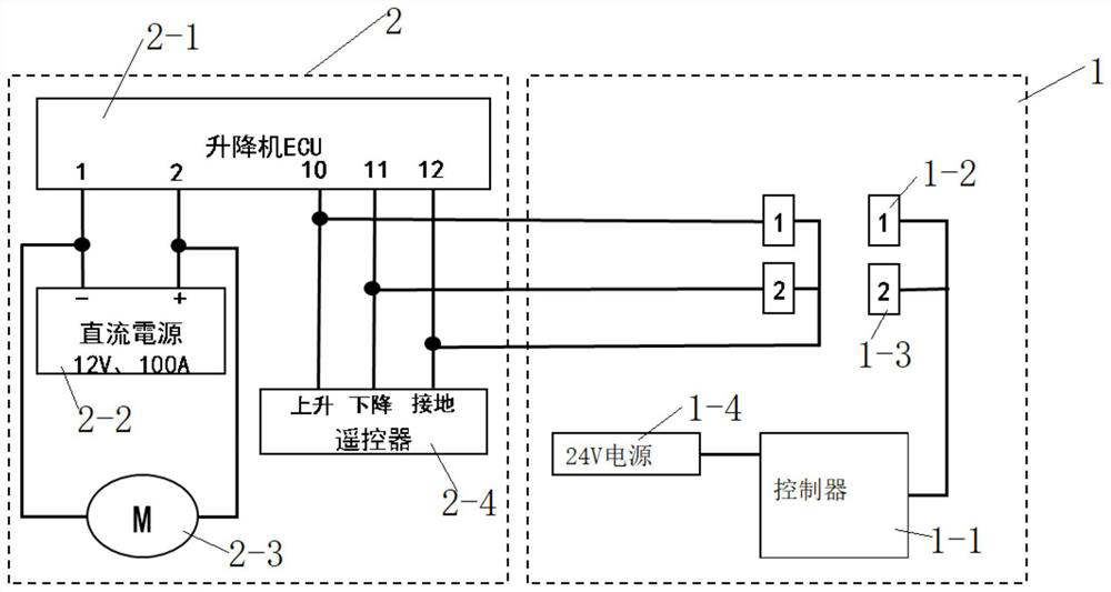
[0070] Such as figure 1 As shown, the lifting endurance test method of the wheel chair lift provided by the disclosed embodiments of the present invention includes:

[0071] S101, connecting the control unit to the elevator body circuit;

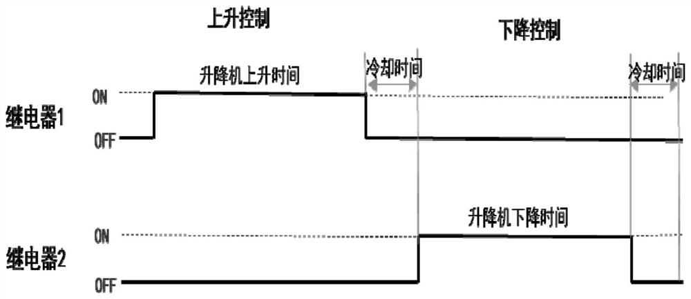
[0072] S102, trigger the ECU control logic embedded in the elevator body through the signal generated by the PLC controller control relay (such a...


PUM


Abstract

The invention discloses a lifting durability test control system, a test method and a terminal of a vehicle and wheelchair lifter, and relates to the technical field of vehicle body function accessory durability test. The control unit is connected into a loop of the elevator body and used for controlling signals generated by the first relay and the second relay through the PLC to trigger ECU control logic of the elevator body, and automatic control over the test process is achieved; the lifter body is used for controlling the lifter to ascend and descend through the carried lifter ECU. According to the invention, the technical problems of inaccurate test actuation times, poor consistency and poor test precision caused by manual control test are eliminated, and the working load of personnel in the test process is reduced. According to the invention, automation of the test process is realized. According to the invention, the control system is connected to the elevator loop, and the PLC controls the signal generated by the relay to trigger the ECU control logic embedded in the elevator body, so that the automatic control of the test process is realized.

Description

technical field [0001] The invention discloses a technical field of durability testing of body function accessories, and in particular relates to a lift durability testing control system, testing method and terminal of a wheelchair lift. Background technique [0002] At present, according to enterprise standards, it is necessary to ensure the durability and reliability of a certain type of welfare wheelchair lift within the service life of the vehicle. During the product development stage, it is necessary to conduct durability tests on wheelchair lifts to verify product reliability. [0003] The development standard stipulates that the number of durability cycles of the product must reach more than 5,000 times. In the absence of corresponding control devices, it is necessary to rely on manual methods to achieve product durability verification. [0004] Through the above analysis, the problems and defects in the prior art are: [0005] (1) The existing equipment cannot meet ...

Claims


Application Information

Patent Timeline
Patent Type & Authority Applications(China)
IPC IPC(8): G01M13/00
CPCG01M13/00
Inventor 程若愚张震胡剑李智徐茂青贵琳
Owner TIANJIN FAW TOYOTA MOTOR CO LTD
Learn More