
Automatic control circuit for differential signal transmission quality

An automatic control circuit and differential signal technology, applied in the direction of program control, computer control, general control system, etc., can solve problems such as inaccurate measured results, difficult to measure accurately, abnormal differential signal transmission, etc., to reduce labor and time costs , reduce economic or property losses, and improve measurement accuracy

Pending Publication Date: 2022-01-11
HIWING TECH ACAD OF CASIC
View PDF3 Cites 0 Cited by
  • Summary
  • Abstract
  • Description
  • Claims
  • Application Information

AI Technical Summary

Problems solved by technology

The transmission of differential signals in actual projects is often not in the state of the lowest power consumption that enables the load to work normally
However, if the design is improper, it is very likely to cause abnormal differential signal transmission, thus investing a lot of manpower and material resources for corresponding bad analysis; more seriously, it will lead to the failure of the entire project, resulting in huge economic or property losses
[0003] At the same time, since the differential signal traces in actual projects are very thin, most of them are in the range of tens of um, and in the bad analysis of the abnormal differential signal transmission, the probes of the test equipment used are all at the mm level, and it is difficult to achieve accurate measurement
In this case, it is inevitable to increase the distance between differential lines or perforate and change layers, or to expose copper in the middle of the transmission line, which may further introduce other interference factors, thereby affecting the accuracy of measurement results.
[0004] In addition, for the detection of differential signal transmission quality, the actual best position to be measured should be the intersection of the transmission line and the load, and the existing technical capabilities are only limited to testing and acquisition in the middle of the transmission line, so that the measured inaccurate result

Method used


Image

  • Automatic control circuit for differential signal transmission quality
  • Automatic control circuit for differential signal transmission quality
  • Automatic control circuit for differential signal transmission quality

Examples

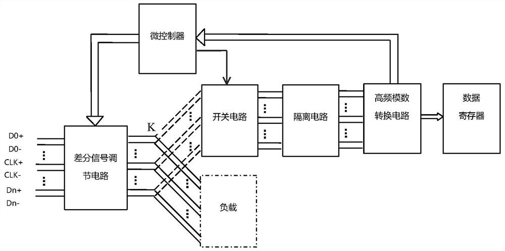

Embodiment Construction

[0029] The present invention will be described in further detail below in conjunction with the accompanying drawings.

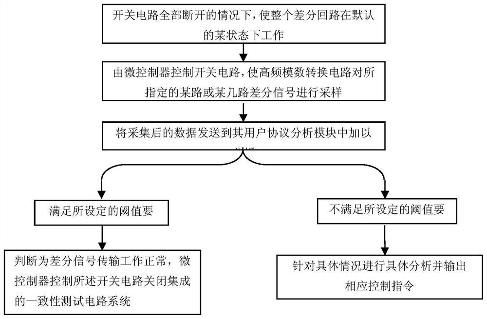
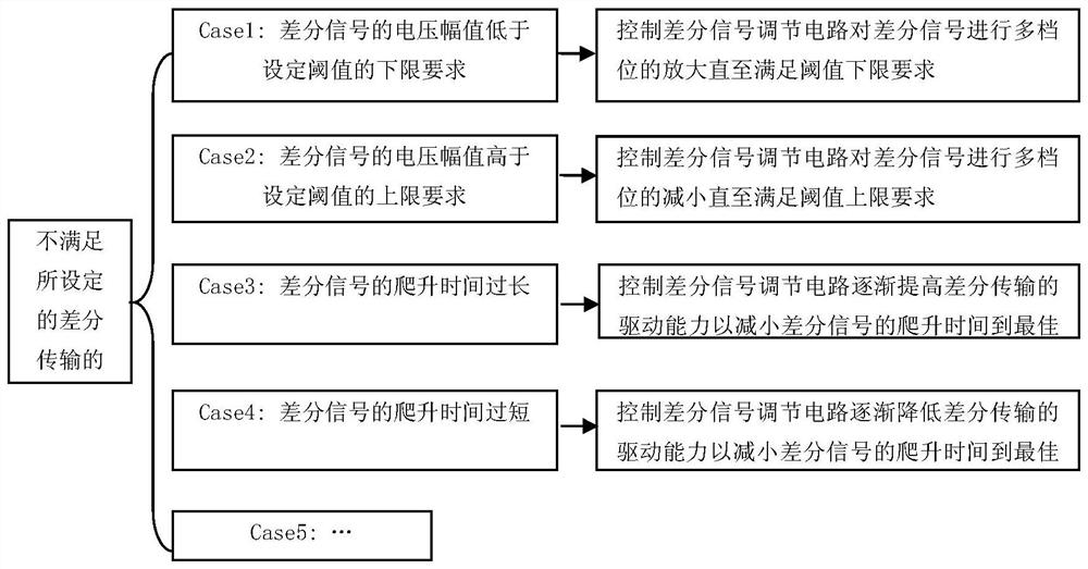
[0030] The invention detects the quality of the differential signal based on the integrated consistency test circuit, specifically analyzes the detection result and outputs a corresponding adjustment scheme, so as to realize the automatic optimization and compensation function of the differential signal transmission.

[0031] like figure 1 As shown, the integrated conformance test circuit includes: a differential signal conditioning circuit, a switch circuit, an isolation circuit, a high-frequency analog-to-digital conversion circuit, a data register and a microcontroller.

[0032] Specifically, the differential signal adjustment circuit is connected in series between the differential line and the load, assuming that the cross point between it and the load and the switch circuit is K point, it realizes the multi-level amplification or reduction of the differe...


PUM


Abstract

The invention relates to an automatic control circuit for differential signal transmission quality. The automatic control circuit comprises a differential signal adjusting circuit, a switching circuit, an isolating circuit, a high-frequency analog-to-digital conversion circuit, a data register and a microcontroller. The differential signal adjusting circuit is connected in series between the differential line and the load, the differential line testing branch is connected in parallel to the intersection position of the differential line and the load through the switching circuit, and the isolating circuit is located between the switching circuit and the high-frequency analog-to-digital conversion circuit. The microcontroller controls the switching circuit, so that the high-frequency analog-to-digital conversion circuit collects a certain path or several paths of specified differential signals, the microcontroller receives collected data, sends out a corresponding instruction according to a preset adjustment scheme, and controls the differential signal adjustment circuit to carry out corresponding adjustment, and meanwhile, data acquired by the high-frequency analog-to-digital conversion circuit is stored in a data register. According to the invention, optimization compensation with higher efficiency and lower power consumption under the abnormal condition of high-speed differential transmission is realized.

Description

technical field [0001] The invention belongs to the technical field of high-speed communication, in particular to a circuit for automatically controlling transmission quality when high-speed signals are transmitted through differential lines. Background technique [0002] With the rapid development of science and technology, high-speed signals are often transmitted through differential transmission schemes to improve anti-interference capabilities. When the differential signal transmission rate exceeds 1GHz in practical applications, the control of its signal quality becomes particularly critical. The transmission of differential signals in actual projects is often not in the state of the lowest power consumption that enables the load to work normally. However, if the design is improper, it is likely to cause abnormal differential signal transmission, and a lot of manpower and material resources will be invested in the corresponding bad analysis; more seriously, it will lea...

Claims


Application Information

Patent Timeline
Patent Type & Authority Applications(China)
IPC IPC(8): G05B19/042
CPCG05B19/0423
Inventor 李良梁李增良高翔
Owner HIWING TECH ACAD OF CASIC
Learn More