Decondensation temperature control system

A technology for controlling the system and condensation temperature, which is applied in the direction of electrical components, panel/switch station circuit devices, substation/switch device cooling/ventilation, etc., which can solve the damage of electrical components, increase the space occupied by the decondensation device, Large damage to electrical components, etc., to achieve the effect of reducing the effect

Pending Publication Date: 2022-01-11
江苏普菲克电气科技有限公司
View PDF0 Cites 0 Cited by
  • Summary
  • Abstract
  • Description
  • Claims
  • Application Information

AI Technical Summary

Problems solved by technology

Due to the temperature difference, condensation will occur on the inner wall. When the condensation is severe, the condensed dew will drip on the electrical components in the distribution box, causing damage to the electrical components, resulting in a high damage rate, especially in the distribution box. When condensation occurs on the top of the wall, the condensed water droplets will fall vertically and directly fall on the electrical components. Compared with the condensation on the side wall, the condensation at this place will cause greater damage to the electrical components
[0003] At present, the decondensation device that uses physical desiccant for dehumidification will temporarily lose the dehumidification effect when the physical desiccant is dehydrated. At this time, another method is required for dehumidification. Some distribution boxes are equipped with another set of dehumidification equipment. Dehumidification, but this will increase the floor space of the decondensation device. Some distribution boxes have a compact internal structure, which increases the space load of the distribution box

Method used


Image

  • Decondensation temperature control system
  • Decondensation temperature control system
  • Decondensation temperature control system

Examples


Embodiment Construction

[0024] In the description of the invention, it is to be noted that the term "mount", "connected", "connection", such as a fixed connection, unless otherwise expressly specified and defined, unless otherwise expressly specified and defined. Connect, or integrate; may be mechanical connection, or electrical connection; may be directly connected, or indirectly connected by an intermediate medium, which can be in the interior of the two elements. For those skilled in the art, the specific meaning of the above terms can be understood in the art.

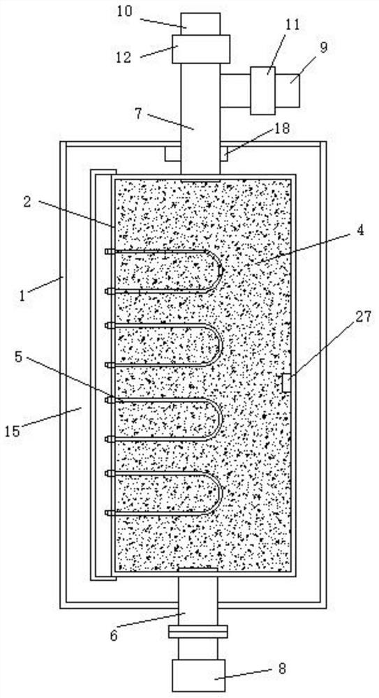
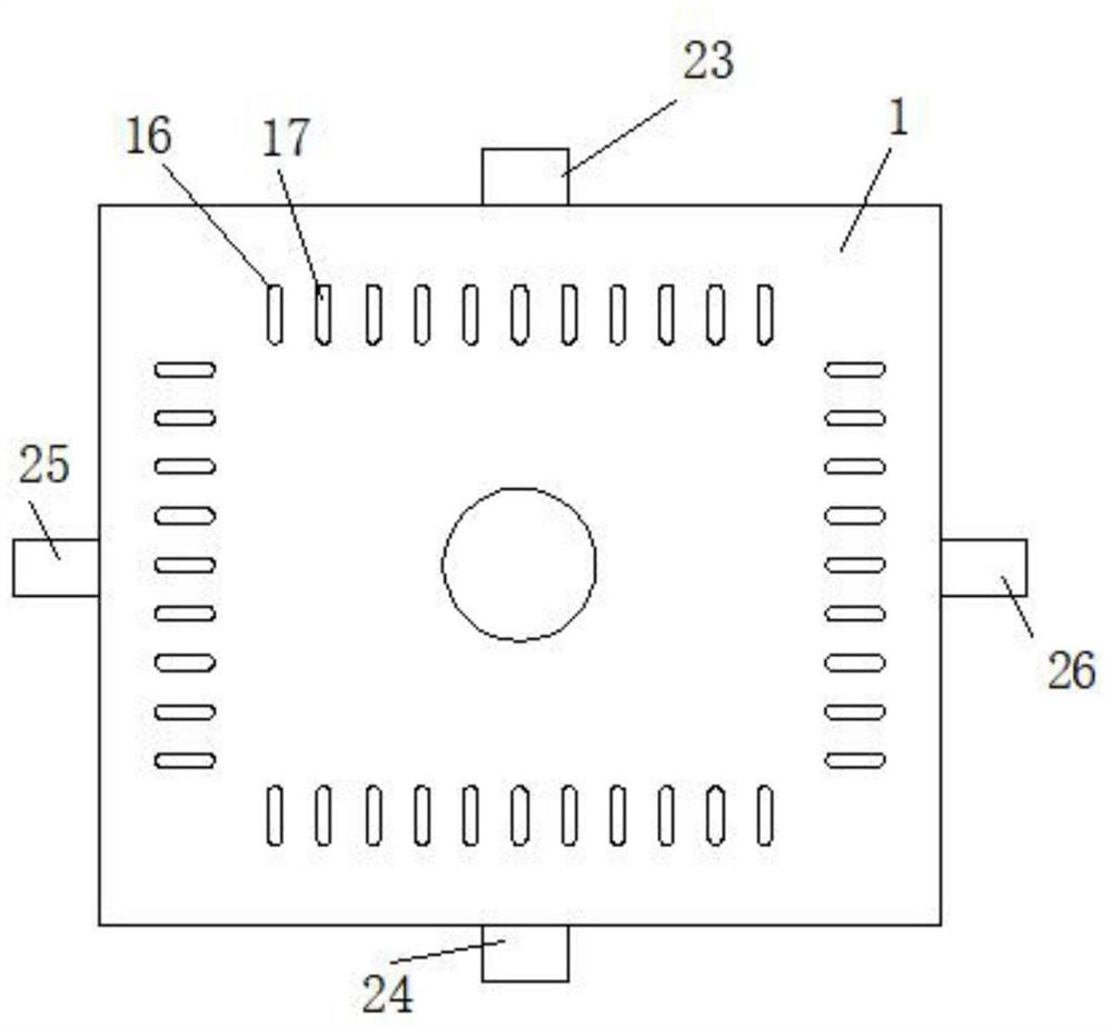
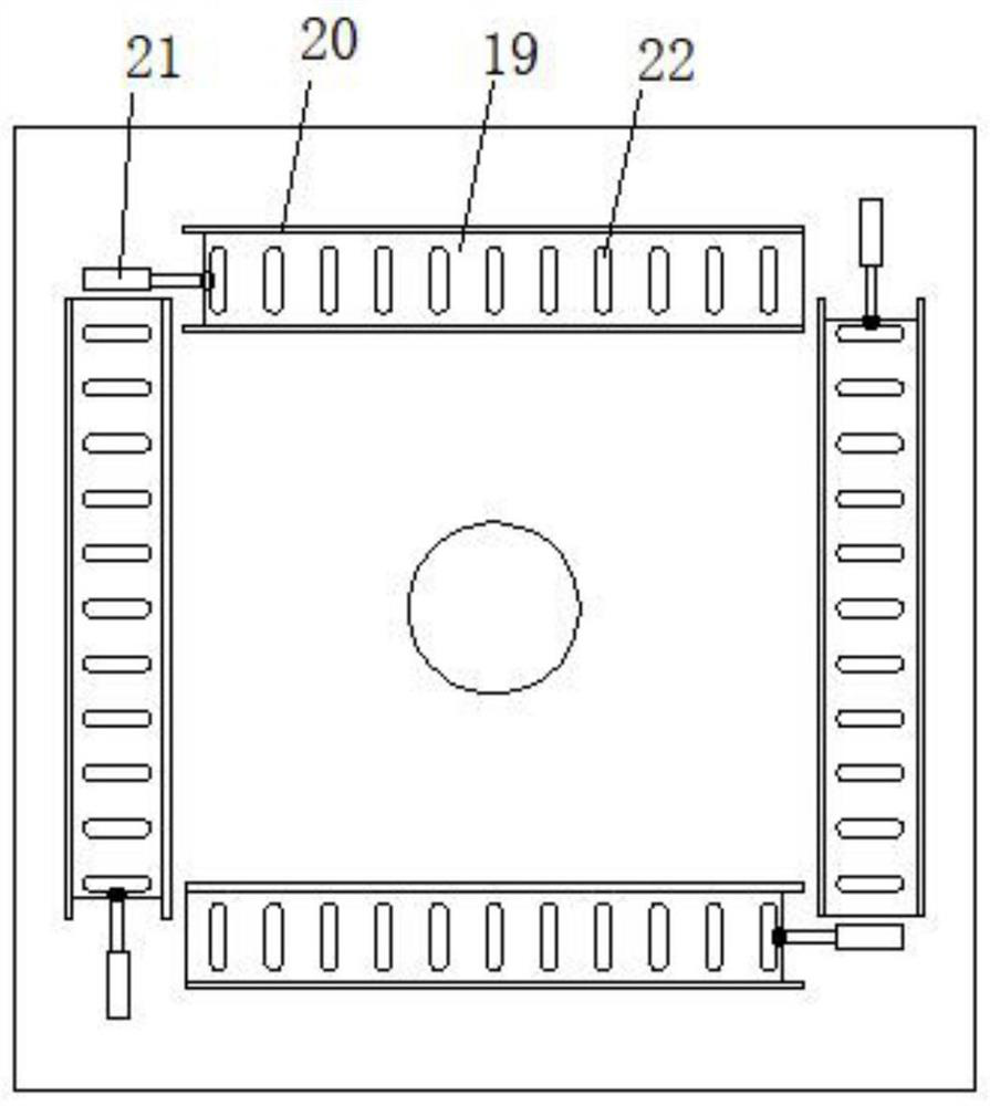
[0025] like Figure 1-5 As shown, a de-condensed temperature control system includes an outer casing 1, a dehumidifier 2, a controller 3;

[0026] The outer casing 1 is disposed in the distribution box.

[0027] The intrinsic desiccant 4 is filled in the dehumidification tank 2, the physical desiccant 4 employs one of active alumina, silica gel, activated carbon, a mineral desiccant, a molecular sieve desiccant, a clay desiccant, and the like....


PUM


Abstract

The invention discloses a decondensation temperature control system, which comprises an external box body and a dehumidification box. The outer box body is arranged in the distribution box, a supporting frame is arranged between the mounting plate and a bottom plate of the outer box body, the dehumidification box is arranged on the mounting plate, an air channel is formed between the dehumidification box and the outer box body, an air inlet window is arranged on a front panel of the outer box body, a second fan is arranged on a rear panel of the outer box body, and an air outlet pipe of the second fan extends out of the distribution box; when the dehumidification box is used for dehydration and cannot be used for dehumidification, the temperature of the external box body is increased by using the heating temperature during dehydration of the dehumidification box, the external box body plays a role in heating air in the distribution box at the moment, and after the internal temperature is increased, the standard moisture content of the air is increased, and condensation is not easy to generate; and meanwhile, external box body temperature control is arranged, so that the temperature is not too low, the condensation removal effect is reduced, and other circuit components in the distribution box cannot be damaged due to too high temperature.

Description

Technical field [0001] The present invention relates to the technical field of distribution boxes, and more particularly to a de-condensed temperature control system. Background technique [0002] The distribution box is widely used in power plants, oil, chemicals, metallurgy, textile, high-rise buildings, etc., as used as power transmission, distribution and electrical energy conversion, some of the damp coagulation problems in some distribution boxes, resulting in internal distribution boxes There are many reasons for condensation. Due to the temperature difference, it will cause condensation in its inner wall. When the condensation is severe, the condensed dew drops will drop on the electrical components in the distribution box, resulting in damage to the electric component, resulting in high damage ratio, especially the distribution box. At the top, when condensation occurs, the condensed water droplets are vertically dropped directly on the electrical components, compared to...

Claims


Application Information

Patent Timeline
Patent Type & Authority Applications(China)
IPC IPC(8): H02B1/56H02B1/24
CPCH02B1/565H02B1/24
Inventor 王莹郭修原沈为东郭月霞匡蔚汤俊
Owner 江苏普菲克电气科技有限公司
Why Eureka
Try Eureka