
Autotransformer step-down control system based on PLC

A technology of autotransformer and control system, which is applied in the field of transformer control, can solve problems such as autotransformer overheating, reduced starting reliability, unfavorable intermediate relay, etc., and achieves the effects of stable operation, advanced design concept and simple connection

Pending Publication Date: 2022-01-11
青海引大济湟工程综合开发有限责任公司
View PDF0 Cites 0 Cited by
  • Summary
  • Abstract
  • Description
  • Claims
  • Application Information

AI Technical Summary

Problems solved by technology

Although the current flowing to the autotransformer is small, long-term operation and heavy load start-up will cause the autotransformer to overheat for a long time and eventually burn out the equipment
(3) The normal operation of KM3 must be premised on the KA coil of the intermediate relay being charged for a long time, which is not good for the intermediate relay and will reduce the reliability of the start-up
(4) There is a danger of direct start of the control circuit, which is not allowed

Method used


Image

  • Autotransformer step-down control system based on PLC
  • Autotransformer step-down control system based on PLC
  • Autotransformer step-down control system based on PLC

Examples


Embodiment 1

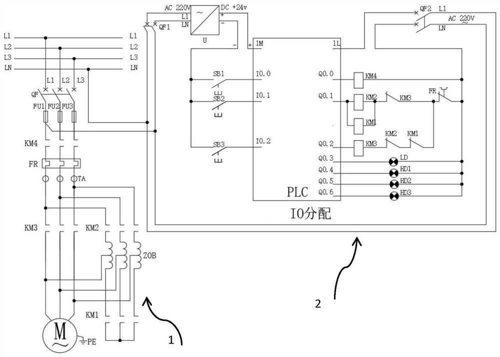
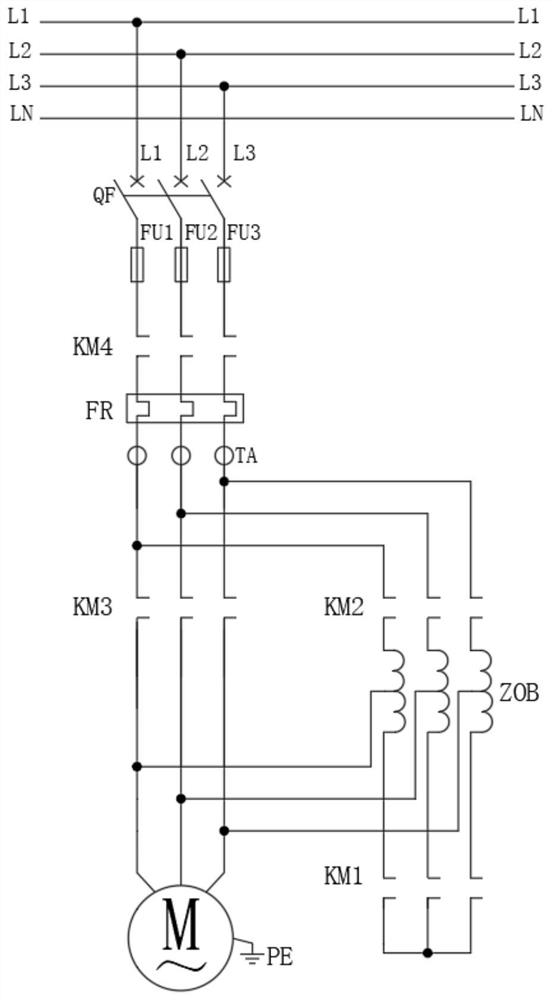
[0028] Please refer to the attached Figure 1-5 , the present invention provides a PLC-based autotransformer step-down control system, the system includes a main power circuit 1 and a control loop 2, wherein the main power circuit 1 is composed of a main power switch QF, a motor M, a fuse FU1, a fuse FU2, fuse FU3, main circuit AC contactor KM4, motor integrated protector FR, current transformer TA, full-voltage operation AC contactor KM3, step-down operation AC contactor KM2, star-point short-circuit AC contactor KM1 and automatic Composed of coupling transformer coil ZOB; the three terminals of the motor M are respectively connected to three live wires L1, L2, L3, and the three live wires L1, L2, L3 between the motor M and the main power switch QF are connected in series with full-voltage running AC Contactor KM3, current transformer TA, motor integrated protector FR, main circuit AC contactor KM4, fuse FU1, fuse FU2, fuse FU3; the first end of the autotransformer coil ZOB i...

Embodiment 2

[0033] Based on Example 1, as attached Figure 1-5 , the system works as follows:

[0034] The main circuit AC contactor KM4 is used to provide power supply for the whole set of circuits, and is used to supply power to the main power circuit 1 in the present invention. That is, close the main circuit AC contactor KM4 before starting, otherwise the main power circuit 1 and control circuit 2 of the entire system will be without power.

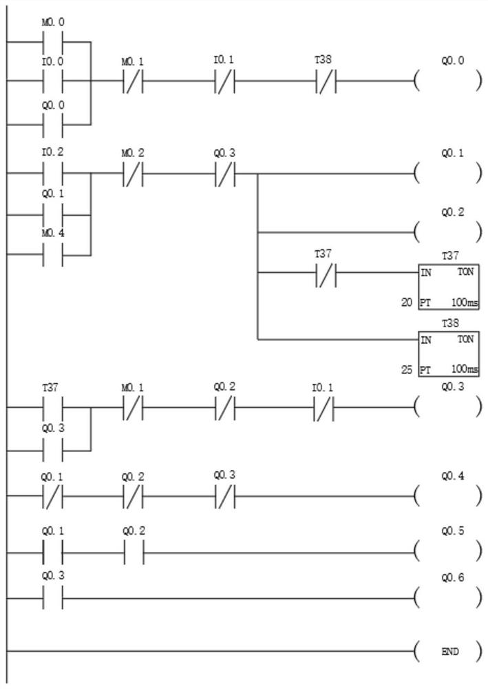
[0035] In addition, the PLC internal relay is used to monitor whether the full-voltage running AC contactor KM3 is closed, to prevent star-point short-circuiting of the AC contactor KM1, step-down running AC contactor KM2 jamming or contact welding, and poor contact of the auxiliary contact. And the protection measures that cause the autotransformer to run in the starting state all the time. In order to prevent such accidents, there is a time difference in the programming of the PLC, and the timer starting with the letter "T" inside the PLC is ...


PUM


Abstract

The invention relates to the technical field of automatic control, in particular to an autotransformer step-down control system based on a PLC. The system comprises a main power circuit and a control loop. According to the autotransformer step-down control system based on the PLC, an XJ01 autotransformer control loop is improved based on the PLC and touch screen control, and a main loop alternating current contactor KM4 is additionally arranged on a main loop. When a star point is in short circuit with the alternating current contactor KM1, the alternating current contactor KM2 is in voltage reduction operation, and contacts are adhered, a timer T38 in the PLC detects abnormity, and a main loop alternating current contactor KM4 sends out an immediate tripping command to protect a motor and an autotransformer. According to the scheme, the design concept is advanced, and the PLC and the touch screen are adopted to run stably, safely and reliably; compared with the original wiring mode, the connection is simple; and maintenance is convenient, and even if internal data are lost, the data can be recovered within several minutes.

Description

technical field [0001] The invention relates to the technical field of transformer control, in particular to a PLC-based autotransformer step-down control system. Background technique [0002] Autotransformer control wiring is no stranger to professionals in the electrical industry, and it is mainly used for starting high-power motors. Under normal circumstances, the direct start method cannot be used to start a motor with a motor power greater than 11kW. [0003] When the autotransformer step-down starts the motor, the autotransformer is used to reduce the voltage applied to the stator winding of the motor. After the motor is started, the motor is separated from the autotransformer so that it can move normally under full voltage. This step-down start is divided into manual control and automatic control. There is a problem that the control wiring of the autotransformer is easy to burn out. The easy burnout of the XJ01 series auto step-down transformer is often caused by t...

Claims


Application Information

Patent Timeline
IPC IPC(8): H02H7/08H02P25/18H02P1/26
CPCH02H7/08H02H7/0833H02P25/18H02P1/26
Inventor 王熠金辰杰
Owner 青海引大济湟工程综合开发有限责任公司
Learn More