Large-section connecting structure and tool for supercavitation high-speed navigation test prototype

A technology of connection structure and navigation test, applied in the direction of ships, etc., can solve the problems of safety accidents, deviation of the trajectory of the aircraft from the predetermined trajectory, complex structure, etc., and achieve the advantages of simple manufacturing process and process, reducing the difficulty of processing and manufacturing, and improving the test efficiency. Effect

Pending Publication Date: 2022-01-14
NORTHWESTERN POLYTECHNICAL UNIV
View PDF1 Cites 1 Cited by
  • Summary
  • Abstract
  • Description
  • Claims
  • Application Information

AI Technical Summary

Problems solved by technology

The first point is that the connecting thread is prone to loosening, which will cause the large section of the aircraft to rotate axially relative to each other, and cause the preset rudder angle of the cavitator to deviate from the longitudinal plane of the aircraft, thereby causing the aircraft trajectory to deviate from the predetermined trajectory. A security incident occurred
The second point is that the cabin section needs to be rotated when the test prototype is assembled, and the cables passing through the cabin section will be twisted, which will cause problems such as circuit cable breakage and unreliable connection.
[0009] The existing patent No. CN112344808A, the name is plug-in structure and cabin assembly, this patent provides a connection method for aircraft cabins with a diameter of more than 1 meter, which uses the connection method of spigots and screws, but does not use threaded connections If it is scaled down and used for cross-media aircraft with a caliber of less than 200, it cannot guarantee the impact resistance when it

Method used


Image

  • Large-section connecting structure and tool for supercavitation high-speed navigation test prototype
  • Large-section connecting structure and tool for supercavitation high-speed navigation test prototype
  • Large-section connecting structure and tool for supercavitation high-speed navigation test prototype

Examples


Embodiment

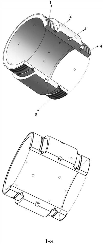
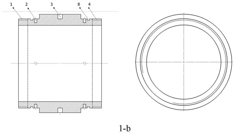
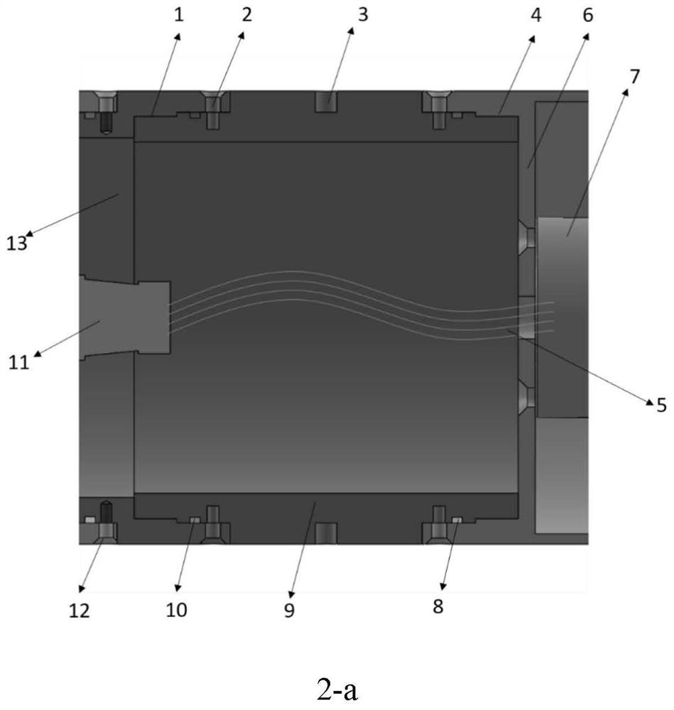
[0053] When the aircraft can withstand an axial load of up to 80g, when selecting the size of the connecting thread, the wall thickness of the thread is not less than 8mm, the thread length is not less than 15mm, and coarse threads are used as much as possible; 8 radial Evenly distributed set screws should be at least M3, and should not be too large, which would damage the shape of the aircraft; the thickness of the step surface of the connecting section should not be less than 6mm, if it is too large, the internal area of ​​the connecting section will be too small, causing the internal Cables take up less space and can cause cable tangles.

[0054] The assembly of the connection structure of the present invention uses such as figure 2 As shown, the left-handed thread 1 at the front of the connection structure cooperates with the left-handed internal thread at the rear of the front cabin, and the right-handed thread 4 at the rear of the connection structure cooperates with th...


PUM


Abstract

The invention discloses a large-section connecting structure and tool for a supercavitation high-speed navigation test prototype, and belongs to the technical field of underwater vehicle high-speed navigation tests. The connecting structure is a straight cylinder with two open ends, the peripheral surface of the connecting structure is of a stepped structure in the axial direction, and the outer diameters of the two ends are smaller than the outer diameter of the middle. Reverse threads are arranged at the two ends of the peripheral face, the left-hand thread end is connected with the front cabin section, the right-hand thread end is connected with the rear cabin section, and synchronous screwing of the front cabin section and the rear cabin section is achieved. A step surface of the peripheral surface is a spigot matching surface and is used for axially limiting when the front cabin section and the rear cabin section are screwed; a plurality of fastening threaded holes are formed in the thread roots of the two ends of the connecting structure in the circumferential direction, and fastening screws penetrate through the through holes in the circumferential walls of the front cabin section and the rear cabin section in the radial direction of the connecting structure to be screwed into the fastening threaded holes. According to the connecting structure, through reverse threaded connection, the reliability of connection is improved, the water tightness of the aircraft is ensured, and the influence of the severe working environment of the aircraft in the test on the aircraft and the phenomenon of cable winding in the aircraft assembling process are eliminated.

Description

technical field [0001] The invention belongs to the technical field of high-speed navigation tests of underwater vehicles, and in particular relates to a large-section connection structure and tooling of a supercavitation high-speed navigation test prototype. Background technique [0002] Using the supercavitation drag reduction technology, the underwater vehicle can achieve a cruising speed of more than 200 knots. During disturbance or maneuvering, the periodic oscillation of the tail will be induced, that is, the tail of the aircraft slaps the cavity wall, which is usually called tail flapping motion. When the tail is in motion, the force on the tail of the aircraft will form a large bending moment on the center of mass, which has a strong destructive effect on the structure of the aircraft, usually causing loosening of the connecting structure and causing greater oscillations, eventually leading to the movement of the aircraft Instability, structural damage, seal failure...

Claims


Application Information

Patent Timeline
IPC IPC(8): B63B79/20B63B73/20B63B73/40B63B73/60
CPCB63B79/20B63B73/49B63B73/20B63B73/60B63B2221/08
Inventor 袁绪龙高裕浩单永志王鹰赵文迪
Owner NORTHWESTERN POLYTECHNICAL UNIV
Why Eureka
Try Eureka