Bridge deck slab capable of being used for steel-UHPC composite beam bridge, steel channel beam, beam bridge and construction method thereof

A bridge deck and steel channel beam technology, applied in bridges, bridge parts, bridge materials, etc., can solve the problems of poor crack resistance of concrete bridge decks, heavy bridge structure, low span, etc., to improve the crack resistance of pier tops, The effect of improved leaping ability and excellent crack resistance

Pending Publication Date: 2022-01-14
HUNAN UNIV
View PDF0 Cites 1 Cited by
  • Summary
  • Abstract
  • Description
  • Claims
  • Application Information

AI Technical Summary

Problems solved by technology

[0006] The invention provides a bridge deck, a steel channel girder, a girder bridge and a construction method that can be used for a steel-UHPC composite girder bridge, so as to solve

Method used


Image

  • Bridge deck slab capable of being used for steel-UHPC composite beam bridge, steel channel beam, beam bridge and construction method thereof
  • Bridge deck slab capable of being used for steel-UHPC composite beam bridge, steel channel beam, beam bridge and construction method thereof
  • Bridge deck slab capable of being used for steel-UHPC composite beam bridge, steel channel beam, beam bridge and construction method thereof

Examples


Embodiment 1

[0051] A unidirectional rib UHPC deck that can be used in steel-UHPC composite girder bridges.

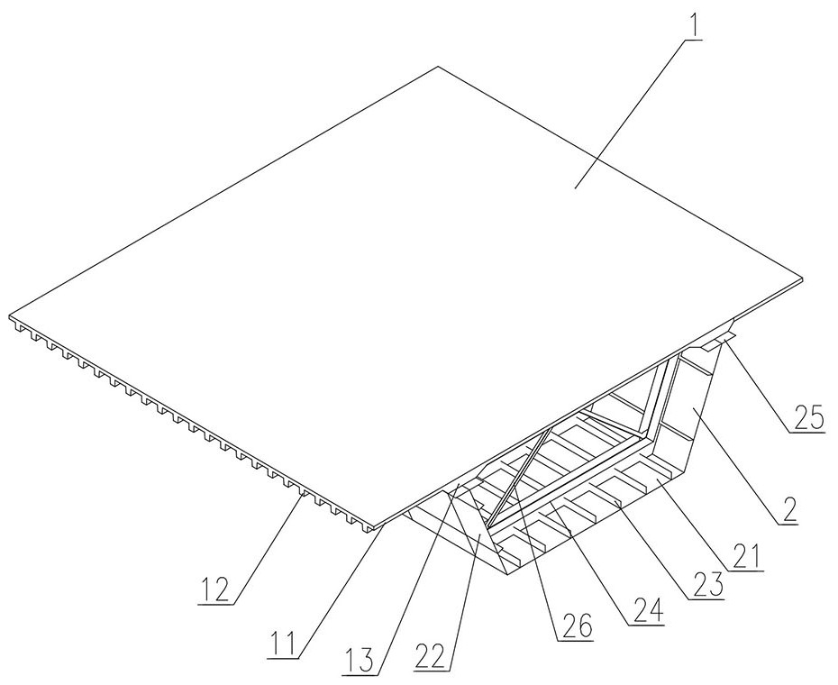
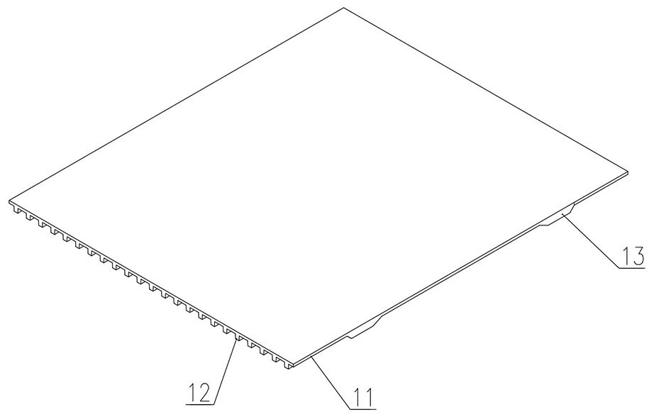
[0052] Such as Figure 1-5 As shown, the unidirectional rib UHPC bridge deck 1 includes a bridge deck body 11, a UHPC transverse rib 12, and a longitudinally thickened portion 13 fixedly connected to the lower steel channel girder 2 of the steel-UHPC composite girder bridge.

[0053] UHPC transverse ribs 12 are arranged under the bridge deck body 11, and the spacing S between two adjacent UHPC transverse ribs 12 is 600mm. The arrangement spacing S is the spacing between the vertical planes of the UHPC transverse ribs 12 along the transverse bridge direction; the bottom surface of the UHPC transverse ribs 12 is provided with steel strips 121, and the thickness of the steel strips 121 is 8 mm. The steel slats 121 are fixed with pegs 122 embedded in the UHPC transverse ribs 12, and the pegs 122 extend upwards from the steel slats 121 into the bridge deck body 11, and there is no brid...

Embodiment 2

[0056] A steel channel girder that can be used in steel-UHPC composite girder bridges.

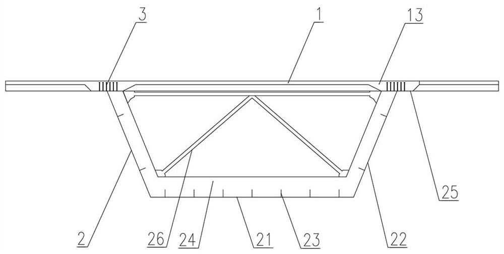
[0057] Such as Figure 6 and 7 As shown, the steel channel beam 2 is a U-shaped channel beam. The steel channel beam 2 includes a bottom plate 21, a web 22 connected to both sides of the bottom plate 21 and a flange plate 25. Both the bottom plate 21 and the web 22 are provided with longitudinal bridges. Stiffener 23, the top of the web 22 is fixed with the flange plate 25 fixedly connected with the one-way rib UHPC bridge deck 1 of embodiment 1, and the flange plate 25 passes through the shear key 3 (this embodiment adopts the peg 122 ) is fixedly connected to the unidirectional rib UHPC bridge deck 1. The web 22 is designed to be inclined, and the surface of the web 22 forms an obtuse angle with the bottom plate 21 .

[0058] The bottom plate 21 and the web 22 of the steel channel girder 2 are also provided with transverse bridge stiffeners 24, which are arranged orthogonally to the l...

Embodiment 3

[0061] A steel channel girder that can be used in steel-UHPC composite girder bridges.

[0062] Such as Figure 8 and 9 As shown, the steel channel beam 2 is a U-shaped channel beam. The steel channel beam 2 includes a bottom plate 21, a web 22 connected to both sides of the bottom plate 21 and a flange plate 25. Both the bottom plate 21 and the web 22 are provided with longitudinal bridges. Stiffener 23, the top of the web 22 is fixed with the flange plate 25 fixedly connected with the one-way rib UHPC bridge deck 1 of embodiment 1, and the flange plate 25 passes through the shear key 3 (this embodiment adopts the peg 122 ) is fixedly connected to the unidirectional rib UHPC bridge deck 1. The web 22 is designed to be inclined, and the surface of the web 22 forms an obtuse angle with the bottom plate 21 .

[0063] The bottom plate 21 and the web 22 of the steel channel girder 2 are also provided with transverse bridge stiffeners 24, which are arranged orthogonally to the l...


PUM

PropertyMeasurementUnit
Thicknessaaaaaaaaaa

Abstract

The invention provides a bridge deck capable of being used for a steel-UHPC (Ultra High Performance Concrete) composite beam bridge, a steel channel beam, a beam bridge and a construction method thereof the bridge deck, and aims to solve technical problems that the steel-UHPC composite beam bridge is overweight in bridge structure, not high in span, poor in crack resistance of a concrete bridge deck and the like. The bridge deck is a one-way rib UHPC bridge deck and comprises a thin bridge deck body and a plurality of UHPC transverse ribs integrally formed at the bottom of the bridge deck body, and the one-way rib UHPC bridge deck is not provided with longitudinal ribs; the steel channel beam is a U-shaped channel beam and comprises a bottom plate, webs connected to the two sides of the bottom plate and flange plates connected to the top faces of the webs, and longitudinal bridge direction stiffening ribs are arranged on the bottom plate and the webs; the beam bridge comprises a plurality of full-hole simply-supported beams which are mutually connected in the longitudinal direction of a bridge, and each full-hole simply-supported beam comprises a one-way rib UHPC bridge deck slab, a steel tank beam and a shear key. The beam bridge adopts a mode that in-plant construction is firstly performed to form a full-hole simply supported beam, and then on-site hoisting is performed. The bridge deck is advantaged in that the self weight of the bridge structure is reduced, stress is reasonable, pier top crack resistance is high, joints are few, construction is easy and convenient, and durability is excellent.

Description

technical field [0001] The invention relates to the field of bridge engineering, in particular to a bridge deck, a steel channel girder, a girder bridge and a construction method thereof which can be used for a steel-UHPC composite girder bridge. Background technique [0002] Sea-crossing bridges are generally composed of navigable bridges and non-navigable bridges. The non-navigable bridges have a long mileage and a large number, and the project scale is much larger than the navigable bridges. Among the typical sea-crossing bridges in my country, the non-navigable bridges account for the total mileage of the bridge. About 70% to 90%. [0003] Therefore, the non-navigation bridge is an important part of the sea-crossing bridge, and it is of great significance to ensure that it is reasonable and economical in construction and safe and durable in operation. Sea-crossing non-navigation bridges mainly include prestressed concrete (PC) girder bridges, steel girder bridges, and st...

Claims


Application Information

Patent Timeline
IPC IPC(8): E01D19/12E01D21/00E01D101/26E01D101/34
CPCE01D19/125E01D21/00E01D2101/268E01D2101/34
Inventor 曹君辉邵旭东邵宗暄邱威溶杨碧川赵宇航
Owner HUNAN UNIV
Why Eureka
Try Eureka