Eureka AIR delivers breakthrough ideas for toughest innovation challenges, trusted by R&D personnel around the world.

Air circulation purification system

A purification system and air circulation technology, applied in air conditioning systems, space heating and ventilation, heating methods, etc., can solve the problems of air purifiers such as high noise, poor purification effect, and slow clean air speed, and achieve noise reduction. Small, Increased Effect, Speeded Effect

Active Publication Date: 2022-01-14
甘肃奥宇科技服务有限公司
View PDF7 Cites 0 Cited by
  • Summary
  • Abstract
  • Description
  • Claims
  • Application Information

AI Technical Summary

Problems solved by technology

[0002] As we all know, with the development of economy and society, the development of modern industrial technology is getting faster and faster, and air pollution is becoming more and more serious. Nowadays, more and more families use air purifiers, which are also called " Air cleaners, air fresheners, and purifiers refer to air pollutants that can absorb, decompose, or transform various air pollutants (generally including PM2.5, dust, pollen, odor, decoration pollution such as formaldehyde, bacteria, allergens, etc.) ), a product that can effectively improve air cleanliness. Due to the persistence and uncertainty of the release of air pollutants in relatively closed spaces, the use of air purifiers to purify indoor air is one of the internationally recognized methods for improving indoor air quality First, the relevant national "Air Purifier" standard defines an air purifier as "a device that separates and removes one or more pollutants from the air. However, the existing air purifiers have low working efficiency and poor purification effect. Good, but at the same time the speed of purifying air is too slow, and the air purifier is too noisy when using high level

Method used


Image

  • Air circulation purification system
  • Air circulation purification system
  • Air circulation purification system

Examples


Embodiment Construction

[0025]The following are specific embodiments of the present invention and in conjunction with the accompanying drawings, the technical solutions of the present invention are further described, but the present invention is not limited to these embodiments.

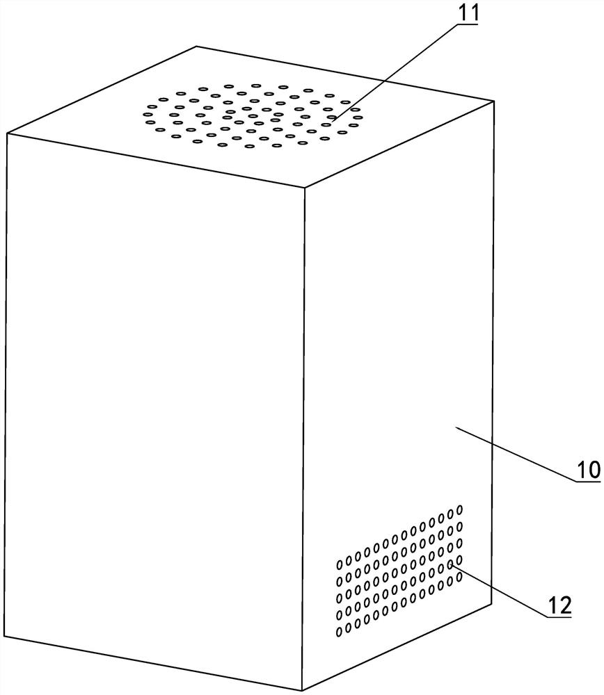
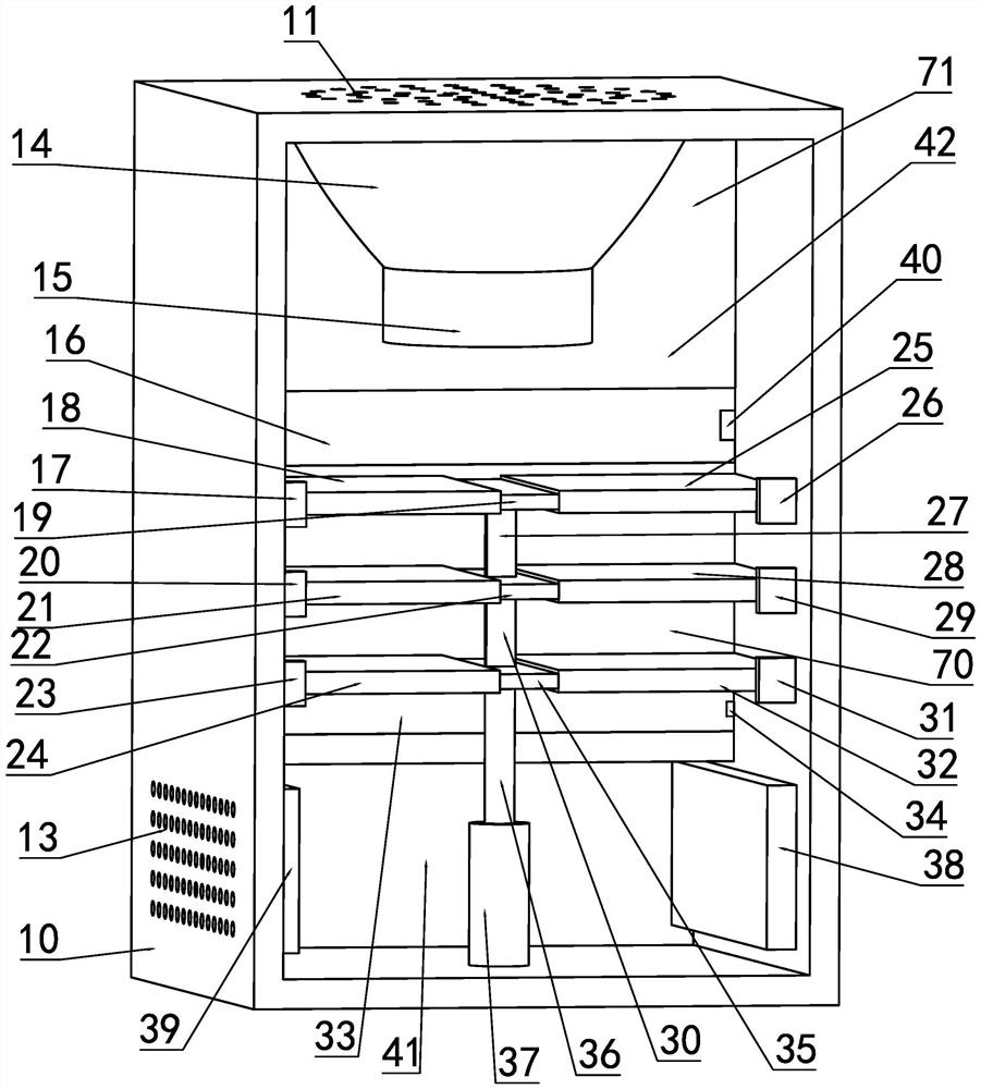
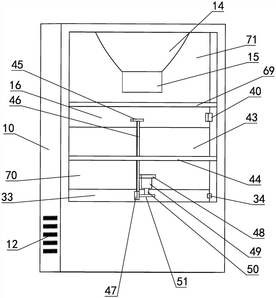
[0026] like figure 1 and figure 2 As shown, an air circulation purification system includes a housing 10, the upper side of the housing 10 is provided with an air outlet 11, the right side of the housing 10 is provided with a right air inlet 12, and the left side of the housing 10 is provided with a left air inlet 13. There is a filter chamber 42 on the upper side of the housing 10, an air inlet chamber 41 on the lower front side of the housing 10, an air outlet chamber 14 is fixed on the upper side of the filter chamber 42, and an outlet chamber is fixed on the lower side of the air outlet chamber 14. Wind channel 15.

[0027] like image 3 , Figure 4 and Figure 5 As shown, four fan motor mounts 56 are fixedly arra...


PUM


Abstract

The invention belongs to the field of air purifiers, and relates to an air circulation purification system. The air circulation purification system comprises a shell, an air outlet is formed in the upper side of the shell, a right air inlet is formed in the right side of the shell, a left air inlet is formed in the left side of the shell, a filtering cavity is formed in the upper portion of the interior of the shell, an air inlet cavity is formed in the front side of the lower portion of the interior of the shell, an air outlet cavity is fixedly formed in the upper side of the filtering cavity, and an air outlet channel is fixedly formed in the lower side of the air outlet cavity. According to the air circulation purification system, air can be purified in a layered mode for multiple times by arranging the multiple layers of purification devices, meanwhile, the inclination angle of the air purification devices can be adjusted by pulling a connecting telescopic plate through a hydraulic rod when a high gear is started, so that the contact area between the air purification devices and the air is increased, the air purification speed is increased, and meanwhile noise generated by high-speed rotation of the fan is reduced; and in addition, air can be circularly purified multiple times, and the air purification effect is improved.

Description

technical field [0001] The invention belongs to the field of air purifiers, in particular to an air circulation purification system. Background technique [0002] As we all know, with the development of economy and society, the development of modern industrial technology is getting faster and faster, and air pollution is becoming more and more serious. Nowadays, more and more families use air purifiers, which are also called " Air cleaners, air fresheners, and purifiers refer to air pollutants that can absorb, decompose, or transform various air pollutants (generally including PM2.5, dust, pollen, odor, decoration pollution such as formaldehyde, bacteria, allergens, etc.) ), a product that can effectively improve air cleanliness. Due to the persistence and uncertainty of the release of air pollutants in relatively closed spaces, the use of air purifiers to purify indoor air is one of the internationally recognized methods for improving indoor air quality. First, the relevan...

Claims


Application Information

Patent Timeline
Patent Type & Authority Applications(China)
IPC IPC(8): F24F8/80F24F8/108F24F8/30F24F8/158
CPCF24F8/80F24F8/108F24F8/30F24F8/158Y02A50/20
Inventor 丁元勤
Owner 甘肃奥宇科技服务有限公司
Why Eureka
Eureka Blog
Learn More